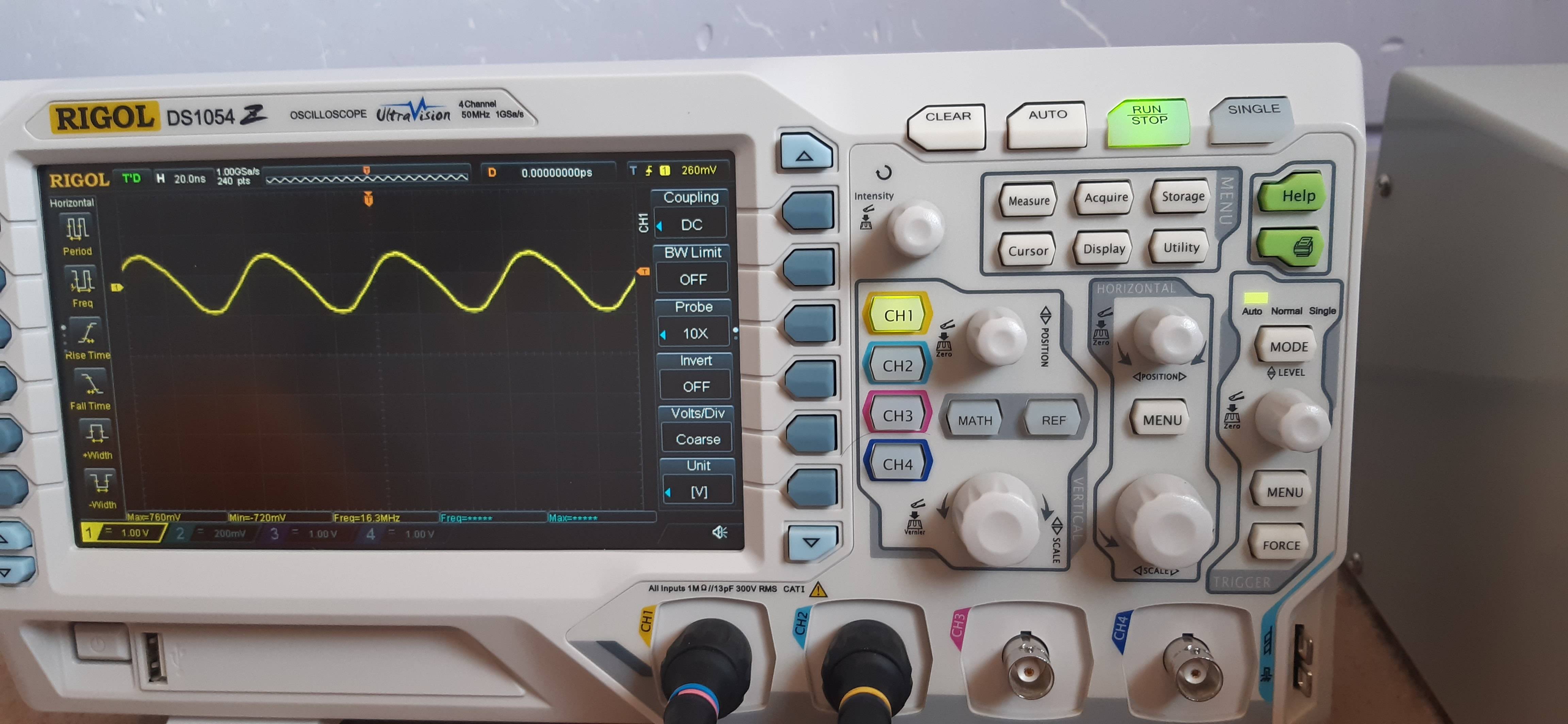
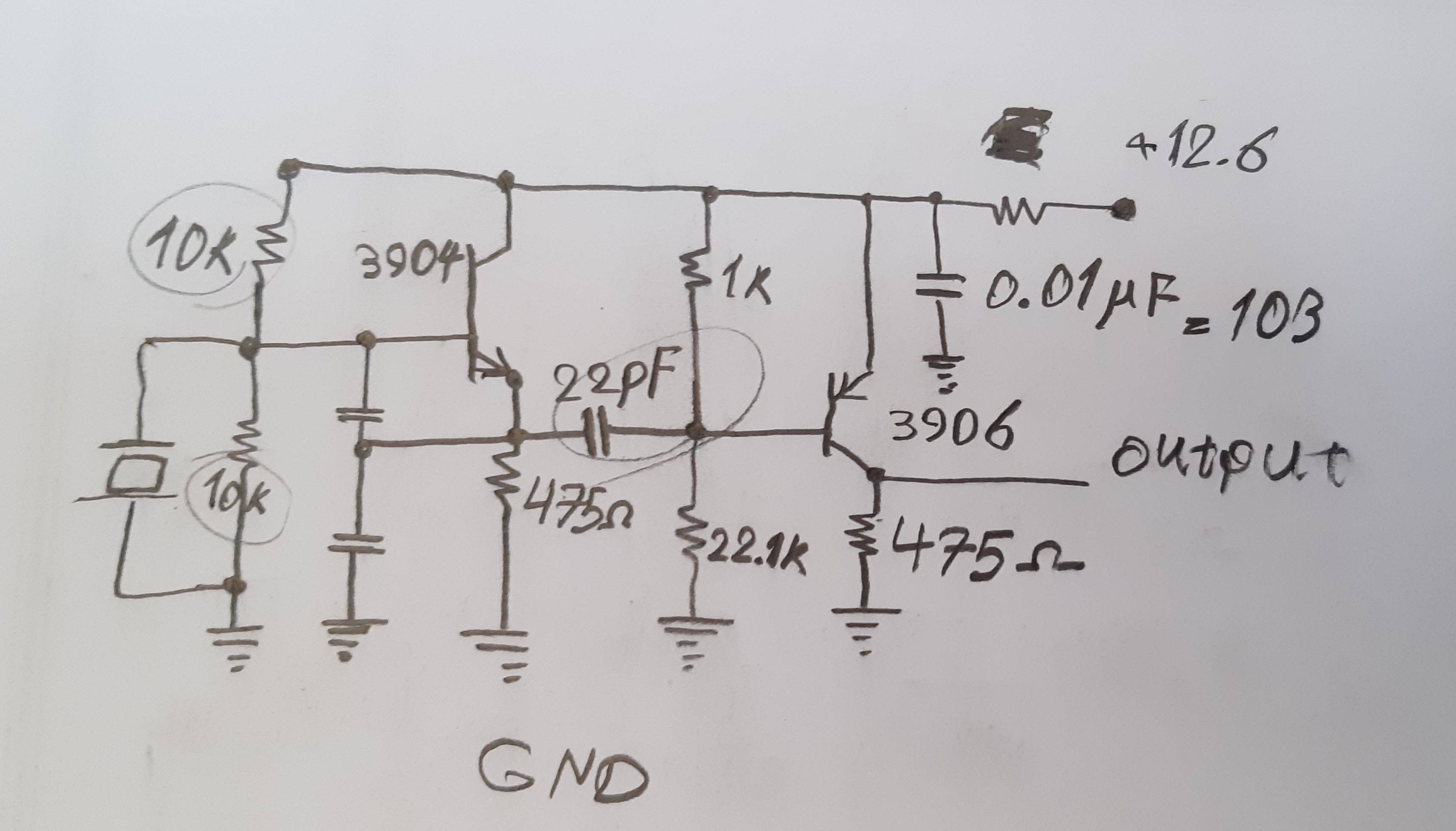
I want to make a driver board for piezo mist maker which requires 10V 1.7MHz signal. So far I have created a signal of 1.7MHz and 0.4 to 0.5V (picture link added) with a crystal oscillator and 2 PNP transistors and bunch of resistors and ceramic caps (picture link added), now I'm trying to pump up voltage on this signal to make something like PWM signal out of this. I have tried comparator on several op-amps but I guess I have chosen them wrong because none of them works. I would be so thankful if you help me or tell me what I'm doing wrong or maybe introduce an op-amp that could work a comparator for me.
-
\$\begingroup\$ Welcome to SE.EE! Please add pictures using the Image button in the editor. Then this question remains valid even when the google drive's content is deleted. (Moreover, personally, I don't trust google drive links.) \$\endgroup\$– HuismanCommented Jul 8, 2019 at 13:11
-
3\$\begingroup\$ Your problem isn't just voltage. You need power to drive the transducer. \$\endgroup\$– JRECommented Jul 8, 2019 at 13:23
-
2\$\begingroup\$ The usual approach is a self-resonant Colpitts oscillator. You want to drive the transducer at resonance and with significant current. Off-resonance, the effectiveness will be significantly reduced. The nominal resonance may be stated as 1.7MHz but the actual frequency will vary from unit to unit and with environmental factors. \$\endgroup\$– Spehro 'speff' PefhanyCommented Jul 8, 2019 at 13:40
-
\$\begingroup\$ Here's a typical 25mm atomiser. That datasheet says it takes up to 30watts. You won't get that out of a simple opamp or transistor circuit. \$\endgroup\$– JRECommented Jul 8, 2019 at 16:08
-
\$\begingroup\$ yes i want the signal to feed it to another mosfet and lc circuit. \$\endgroup\$– KINGCommented Jul 8, 2019 at 16:23
2 Answers
A couple of ideas...
Using an H-bridge to drive both sides of the transducer will double your effective swing available from your supply.
A square wave oscillator that’s filtered with an L-C low-pass will give you roughly the waveform you need.
Such a thing could be constructed from CMOS buffer logic, including the oscillator. Something like the CD4050 for example: http://www.ti.com/lit/ds/schs046j/schs046j.pdf
With both-sides drive it would happily work on 5V, which means you could power it from USB. Keep in mind you can connect the buffers in parallel to boost the drive current even more.
-
\$\begingroup\$ thank you very much I'm a beginner and i want to ask something is my way of creating signal worst inefficient way possible? \$\endgroup\$– KINGCommented Jul 8, 2019 at 16:18
-
\$\begingroup\$ It’s not the worst way, but it isn’t as powerful as it could be. Turns out your application is popular - try googling ‘1.7MHz piezo’ - lots of options, including using CMOS gates as I suggested. \$\endgroup\$ Commented Jul 8, 2019 at 16:29
-
Use 14+V supply with an Op Amp with 150MHz GBW and complementary Darlington inside the feedback loop and drive with a CMOS Oscillator or CMOS Schmitt trigger variable F Oscillator with coarse/fine tuning on f 1 to 3MHz for maximum DC current at resonance using a 50mV drop R sense.
details are easy to web search for this suggested method., even on my answered questions in this site for “high current high GBW Op Amps, Variable F Astable Schmitt CMOS and complementary Darlingtons of FET CMOS bridge “
But for variable power, you can adjust gain and start with “purpose and exact requirements and tolerances”.!!!
- i.e. don’t start with a Mickey Mouse osc.
-
\$\begingroup\$ the way you are proposing is a much more interesting way to create the signal than what I'm doing now but on the other hand it's much more complicated. i searched the internet and found some schematics but how clean is the output signal? and another thing i am feeding the damn circuit about 12 volts but the output is bouncing around .4 to .5 volts is it because of my oscillator system or am i missing something \$\endgroup\$– KINGCommented Jul 8, 2019 at 16:15
-
1\$\begingroup\$ It is a trivial design with lots of power capacity. Yes you are missing everything. Read again and search here for my answers with above key words. \$\endgroup\$– D.A.S.Commented Jul 8, 2019 at 16:17
-


