2
\$\begingroup\$

Guitar Pedal Input

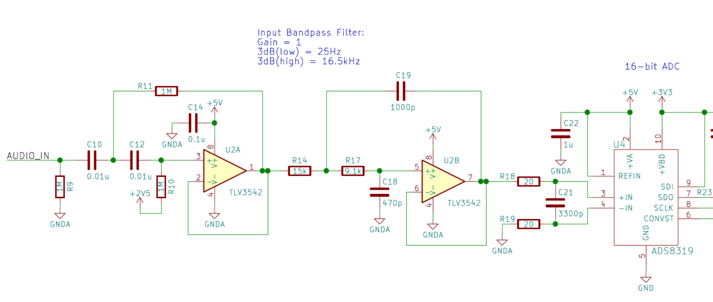
I was reading this report on a digital guitar effects pedal design and I came across the circuit above. "AUDIO_IN" is where the guitar signal enters the pedal. The signal is then filtered through the op amp circuit and ends up at a high res ADC. According to the report, the circuit is a "4th-order unity gain Sallen-Key band-pass filter with cutoff frequencies of 25 Hz and 16.5 kHz".

I set myself to the task of justifying each component and got lost pretty quickly. Here's what I think I know:

R9: Weak pull-down resistor on input to ground

C10, C12: Coupling capacitors (Why are there two?)

R10: Pulls AC signal up into the 0V - 5V range, centered around 2.5V

R11: ???

C14: Decoupling/bypass cap

R14: ???

R17: ???

C18: ???

C19: ???

R18: Resistor in RC filter before ADC input

R19: ???

C21: Capacitor in RC filter before ADC input

I'm really curious about R19. I have a fair amount of experience with DC op amp circuits but I don't have a ton of experience with op amp circuits with AC signals. I want to use this circuit in a project but I want to know what everything does first.

Can anyone help me identify the function of the passives I'm unsure about? Reading suggestions on good AC op amp circuit design are also very welcome.

\$\endgroup\$
1
  • 2
    \$\begingroup\$ It is good you want to struggle to understand the circuit. But your list of questions about it says a lot about what you don't know about Sallen Key. More, it says what you don't know about simple RC filters. If you can, you really should get a book on the topic. Sallen and Key focused on 2nd order and above for filters. But they write well. Perhaps get their paper? \$\endgroup\$
    – jonk
    Commented Aug 30, 2019 at 9:10

3 Answers 3

7
\$\begingroup\$

I think you need to look at it as circuits in stead off individual component.

The first op-amp is a second order high pass filter.

Second op-amp is a second order low pass filter.

Both filters are Sallen-Key topology as jonk wrote in his comment. There is a pretty good wikipedia page on Sallen-Key.

The circuit at the ADC input is a balanced low pass filter. You can read about the circuit in the datasheet for the ADC. The exact circuit can found in the Application and Implementation section.

\$\endgroup\$
5
\$\begingroup\$

Sallen and Key

R. P. Sallen and E. L. Key's 1955 IEEE (IRE) paper, "A Practical Method of Designing RC Active Filters," is worth reading. But even better is their (now) declassified report, R. P. Sallen and E. L. Key, "A Practical Method of Designing RC Active Filters," MIT Lincoln Laboratory Technical Report, No. 50, May 6, 1954 (aka "TR 50".) Either one of these is worth reading, but TR 50 is in my opinion far better. Unfortunately, the US Air Force still has to clear you getting a copy of it and you have to write a justification to do so before MIT will release a copy. (Sadly.)

I have both and I consider them very well worth the time to read. They don't really bother with 1st order filters (I think they figure that's "too easy" to cover.) But they do cover 2nd order and higher, which is very nice. (Appendix I of TR 50, for example, covers both Butterworth and Tschebyscheff.)

The modern interpretation of Sallen-Key filters is usually a 2nd order filter using two resistors (in equal-valued pairs) and two capacitors (also in equal-valued pairs.) They do happen to cover the idea of same-valued components in their paper, but I don't consider it to be the main thrust. So I think it's just popularizers of their ideas, such as Don Lancaster, that has deepened this connection more than the original authors did, themselves. (Sallen and Key were after more theoretical "fish," so to speak.)

If you want, you can refer to a couple of things I wrote here and here. May help. May not.

Sallen and Key HP Filter

For the first stage, the simplest forms of high-pass Sallen-Key filters are:
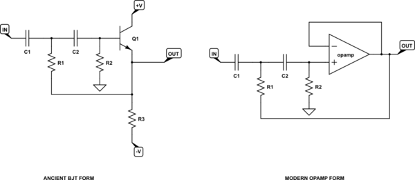
schematic

simulate this circuit – Schematic created using CircuitLab

(I'm including the ancient version just so you can think about it.)

Your first stage looks a lot like the right-hand side (modern) case. If you want, you can read though this EESE link to see how you interpret the above schematic. But when both resistors and both capacitors have the same value and the voltage gain \$K=1\$, then \$\omega_{_0}=\frac1{R\,C}\$ and:

$$\begin{align*}\frac{e_{_\text{out}}}{e_{_\text{in}}} &=\frac{K\cdot \omega_{_0}^2}{s^2+\left(3-K\right)\omega_{_0}\,s +\omega_{_0}^2}=\frac{\omega_{_0}^2}{s^2+2\zeta\,\omega_{_0}\,s +\omega_{_0}^2}\end{align*}$$

You should easily see that with \$K=1\$ then damping factor \$\zeta=1\$, which is a critically damped Butterworth filter. With the values you have in hand for that first stage, you can compute \$\omega_{_0}=\frac1{R=1\:\text{M}\Omega\:\cdot\: C=10\:\text{nF}}=100\$ or that \$f\approx 15.92\:\text{Hz}\$. (The \$2.5\:\text{V}\$ reference that feeds one end of \$R_{10}\$ simply establishes a DC biasing for the opamp input node so that its output will be similarly biased half-way between the rails.)

\$R_9\$ provides a DC path for the input node (good idea) and depending on the source resistance might adjust the exact roll off point. Not likely and I don't think it changes as much as the diagram suggests. So I'm just calling it good enough, for now. Maybe it is my own ignorance.

Sallen and Key LP Filter

For the second stage (low pass), the simplest forms of low-pass Sallen-Key filters are:
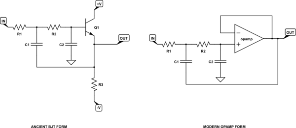
schematic

simulate this circuit

Here again the gain voltage gain is \$K=1\$, but now the resistor and capacitor values are not the same, so \$\omega_{_0}=\frac{1}{\sqrt{R_1\:C_1\:R_2\:C_2}}\$ (I'm just using subscripts 1 and 2 for convenience -- obviously, these don't match the schematic's numbering) and \$\zeta=\sqrt{2}\$. So I get \$f\approx 19.87\:\text{kHz}\$. But since \$\zeta=\sqrt{2}\$, it is over-damped (probably to provide a maximally flat time delay) so the roll-off may occur a little earlier than what \$\omega_{_0}\$ suggests. But again, I didn't go further to verify the given value.

That's as much as I want to add here and I certainly may have made mistakes. But it should provide an approximate overview that helps, at least, identify some of the components you weren't so certain about.

\$\endgroup\$
4
\$\begingroup\$

Great exercise. The other answers provide useful background, but your approach provides some edification and something I always enjoyed (and was frustrated by) when learning electronics. There's always been this "black art" in electronics that is maintained by an adherence to mystery, so many great learnings end up lost. Let's have a crack at providing some rational:

  • R9: Limits noise entering the amplifier when the input is disconnected.
  • C10, C12: The two C's of the two-stage RC high pass filter, arranged according to the Sallen-Key topology
  • R10: Biases signal around 2.5V, as dictated by the Sallen-Key topology.
  • R11: Forms a high pass RC filter with C10, but tied to the output of the filter to bootstrap the input and provide lower input impedance.
  • C14: Decoupling cap for U2.
  • R14: Start of a new Sallen-Key topology, this time a low-pass.
  • R17: Continuation of Sallen-Key topology (provides the second stage low-pass filter).
  • C18: Forms second stage low pass RC filter with R17, as part of Sallen-Key topology.
  • C19: Forms first stage low pass RC filter with R14, as part of Sallen-Key topology.
  • R18: Resistor in RC filter before ADC input
  • R19: Provides matching input impedance on signal path and return path to form a pseudo-differential ADC input, which improves linearity.
  • C21: Capacitor in RC filter before ADC input.
\$\endgroup\$

Your Answer

By clicking “Post Your Answer”, you agree to our terms of service and acknowledge you have read our privacy policy.

Not the answer you're looking for? Browse other questions tagged or ask your own question.