3
\$\begingroup\$

I want to know how to calculate the output of the below op amp. I know this is supposed be an inverting amplifier with offset but I have never seen the connection of the offset to the negative side of op amp.
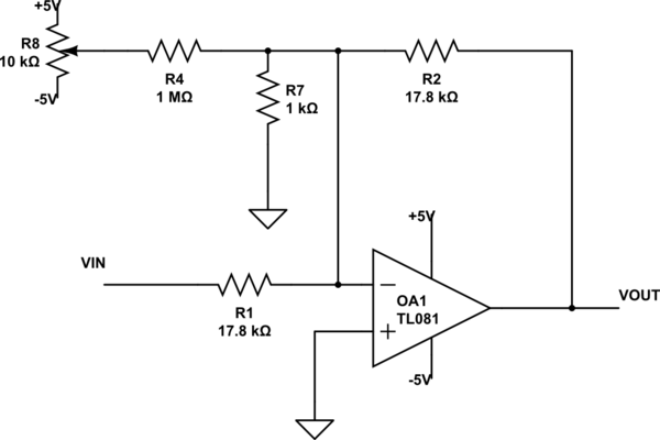
schematic

simulate this circuit – Schematic created using CircuitLab

I have come up with this formula:

$$V_{\text{out}} = V_{\text{in}} \times \frac{R_2}{R_1} + \frac{R_2}{R_4+R_7}V_\text{p}$$

Is it correct? \$V_\text{p}\$ is the voltage out of the potentiometer.

\$\endgroup\$
1
  • \$\begingroup\$ Hint: print this circuit out on paper, and use different colored highlighters to trace out the different nodes. \$\endgroup\$
    – The Photon
    Commented Sep 4, 2019 at 16:33

1 Answer 1

4
\$\begingroup\$

R7 does not do anything of value, it is actually harmful (increases output noise and output offset voltage- and related drift). Ideally there is no voltage across R7 so it has no effect, but op-amps are not ideal and if you think about the resistor approaching zero it's clear there will be problems. You can calculate the effects if you model the op-amp with Vos and Vn voltage in series withe one of the inputs (offset and noise).

Vout ~= \$ -V_{IN} \cdot \frac{R_2}{R_1} -V_P \cdot \frac{R_2}{R_4}\$, ignoring op-amp gain and offset voltage.

You can find that by applying KCL to the non-inverting input node, assuming zero input current to the op-amp and then find Vout such that V- = V+ = 0V.

\$\endgroup\$
1
  • \$\begingroup\$ Isn't the R7 and R1 a voltage divider for the input VIN? Could you please explain why does not do anything to the circuit? Apart from the harmful evects you mentioned \$\endgroup\$
    – MrBit
    Commented Sep 4, 2019 at 20:02

Your Answer

By clicking “Post Your Answer”, you agree to our terms of service and acknowledge you have read our privacy policy.

Not the answer you're looking for? Browse other questions tagged or ask your own question.