0
\$\begingroup\$

I have protoboard, an 8 pin socket adapter and two sets of female header (4 pins).

I want something a little more permanent than a bread board to use when programming ATTiny85s with my Arduino. I think being able to seat the ATTiny into the socket and then access all the pins directly on the female headers will be convenient.

My issue is that I am a super novice at soldering. I seated the header pins right next to the pins for the socket adapter. Then soldered all the socket pins and the header pins. The issue is connecting the two. I read about people who connect solder directly to bridge the adjacent points. And also people who bend pins to make the connection.

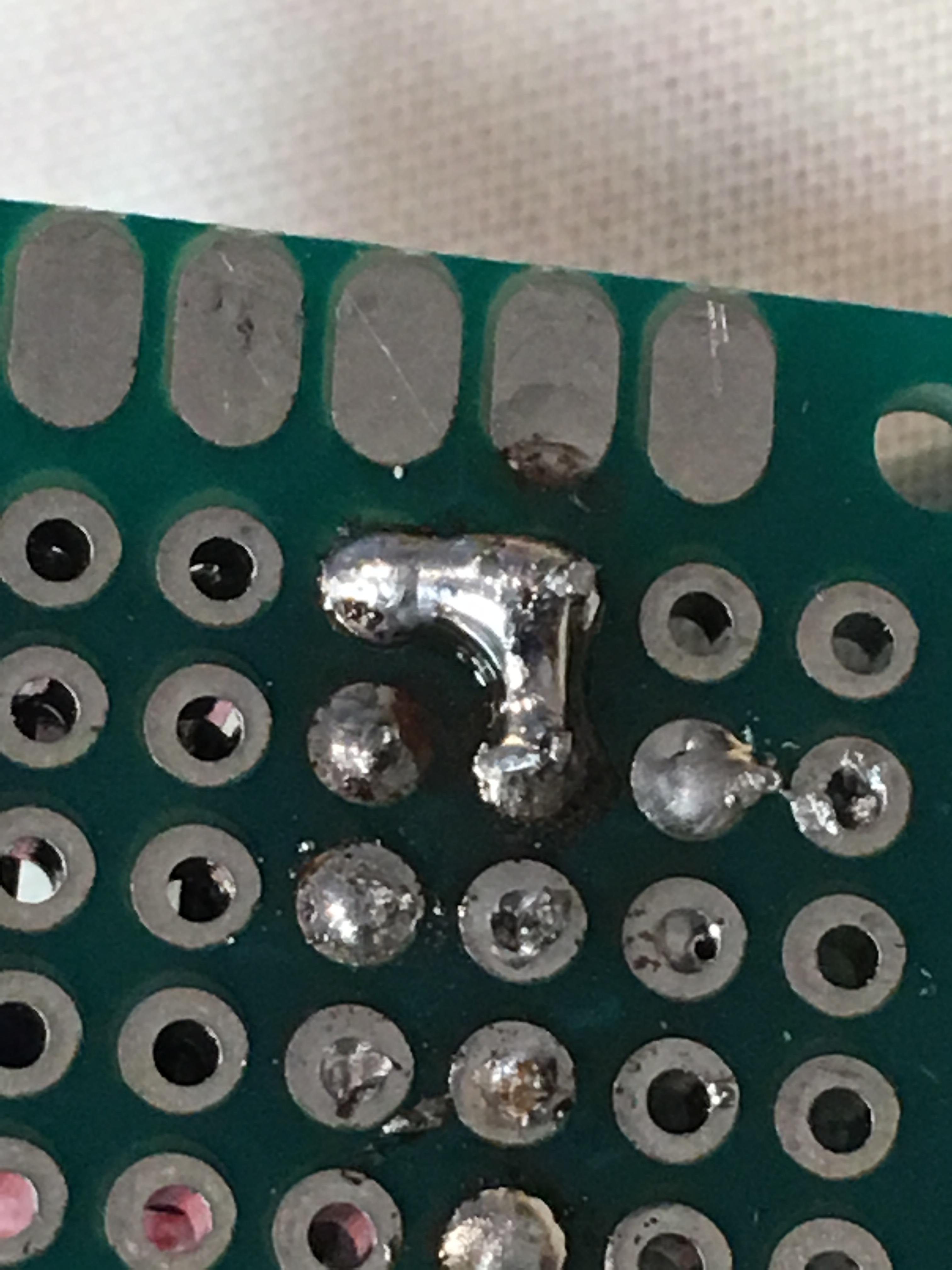
Both sounded like great options to me in theory. The problem was the pins are way too small for me to use the tools I have at my disposal to bend. They wouldn't reach anyways. I thought no problem, I'll just bridge solder from the Female header pin to the appropriate neighboring socket pin. But alas I suck at soldering so I ended up connecting it with the other adjacent solder as well so connecting 3 pins together when I wanted to connect two. enter image description here
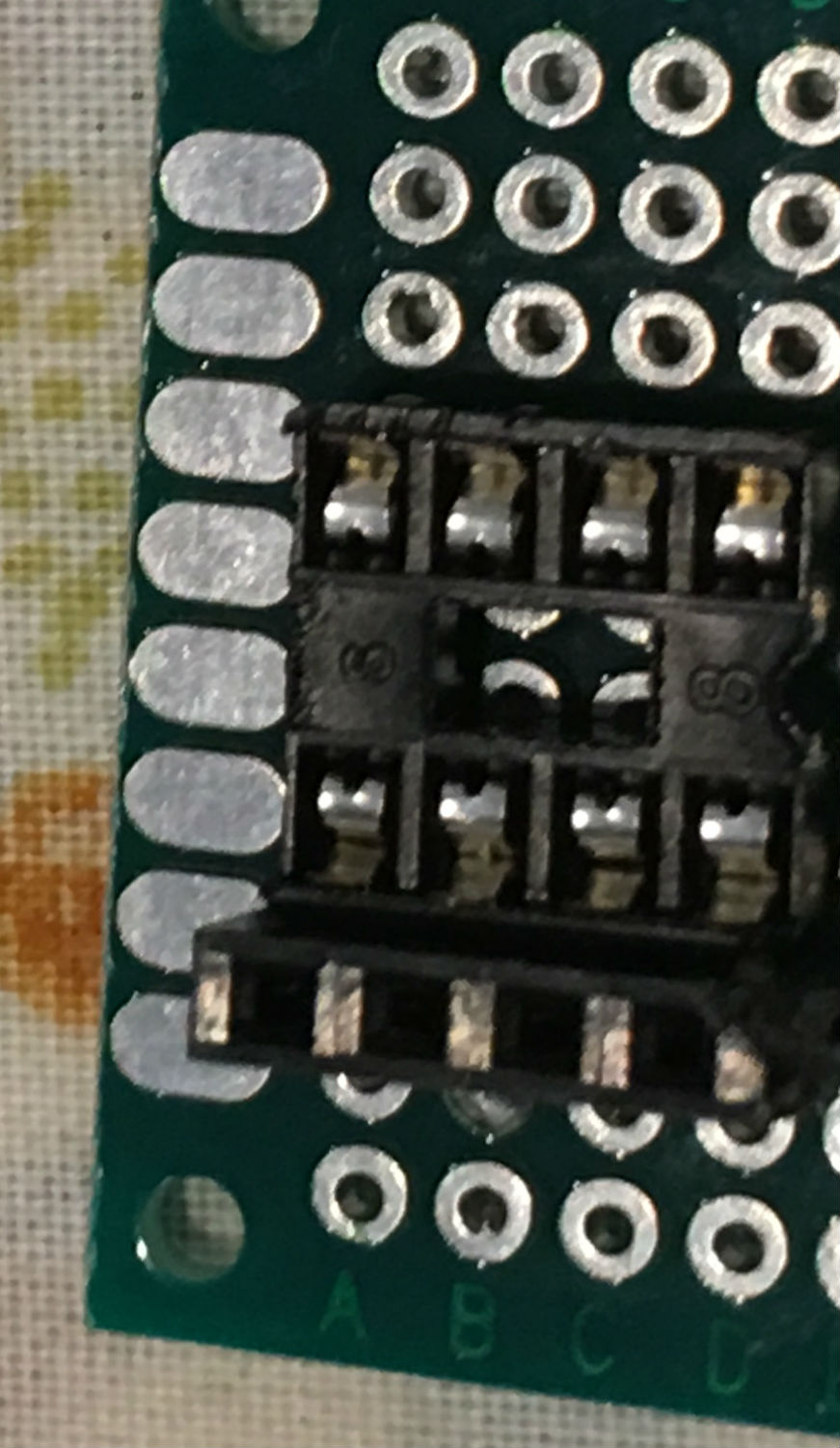
I attempted to cut a little tiny piece of wire and place it in between the two pieces of solder but it wasn't very stable just sitting there so I didn't even try it.

A complete solder fail.

enter image description here

What technique should I be looking at to research to try and solder two adjacent pins together in a crowded area where I don't want to accidentally make a connection to other nearby pins?

\$\endgroup\$
3
  • \$\begingroup\$ please add a picture if you can \$\endgroup\$
    – jsotola
    Commented Sep 15, 2019 at 20:54
  • \$\begingroup\$ I added some photos to clarify \$\endgroup\$
    – Joseph U.
    Commented Sep 15, 2019 at 21:06
  • 2
    \$\begingroup\$ bend short pieces of wire into U shapes that span 2 holes ... drop the U shapes into the perf board all in a row, then push the pin header into the same holes ... solder the pin header pins ... then push in the IC socket and solder \$\endgroup\$
    – jsotola
    Commented Sep 15, 2019 at 21:23

2 Answers 2

1
\$\begingroup\$

Use a PC board that has connections laid out like a plastic breadboard - groups of 5 holes connected together.

\$\endgroup\$
2
  • \$\begingroup\$ I think for a complete novice like me stripboard is probably a good idea. I think this will probably be the direction I go. I also want the ground and power to flow to yet another pin (optionally connected to a battery terminal)your suggestion should save me time and make the connections easier. One question. What is the best way to isolate the right side of the socket connector from the left side since both would share the same row? \$\endgroup\$
    – Joseph U.
    Commented Sep 15, 2019 at 23:06
  • \$\begingroup\$ There are proto-board products with holes and connecting strips laid out exactly like the connections in the plastic breadboards - that's what I was thinking of. There is also "stripboard" (I know it as "Veroboard") that has copper strips running the length of the board. The strips can be easily broken at a hole using a suitable tool, or a drill bit. \$\endgroup\$ Commented Sep 15, 2019 at 23:40
0
\$\begingroup\$

Get some spare pins and practice.

Use a good quality solder with flux and a quality iron which is temperature controllable.

Keep the bit clean and practice...

\$\endgroup\$

Your Answer

By clicking “Post Your Answer”, you agree to our terms of service and acknowledge you have read our privacy policy.

Not the answer you're looking for? Browse other questions tagged or ask your own question.