1
\$\begingroup\$

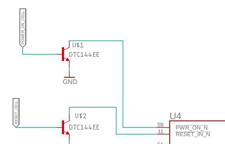
I have connected the collector of a NPN BJT (DTC144EE) to the Power_ON pin of my lte module (HL7588).

The pin is internally pulled up by a 100k resistor to 1.8V. The module is powered on by driving the PWR_ON signal low (I send 1.8V from my controller to the base of U$1). enter image description here
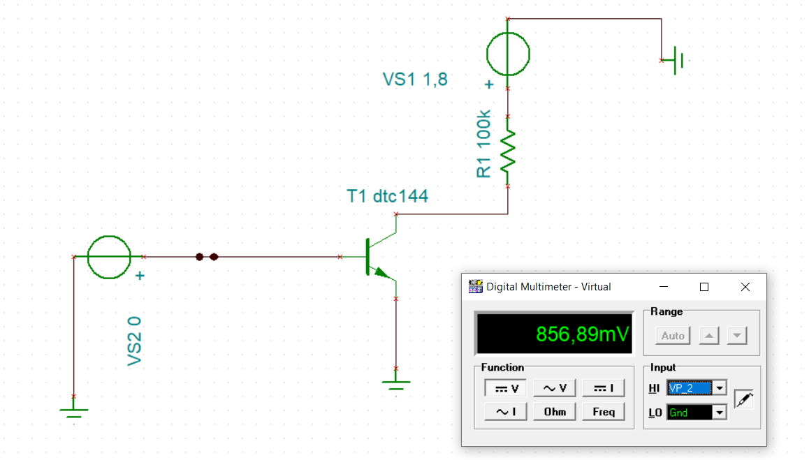
However, I ran a simulation in TINA and am seeing .85V at the collector (when I want device in OFF state) when the minimum of a a high signal should be 1.33V.

enter image description here

On U4s Data sheet:

enter image description here

Any ideas on what is going on here? This is the transistor Sierra recommends for both Power_on and Reset signals so it is confusing.

\$\endgroup\$
6
  • \$\begingroup\$ First, what voltage are you putting on to the base of T1, and second, where is the current-limiting resistor at the base of T1? \$\endgroup\$
    – TimWescott
    Commented Oct 15, 2019 at 20:28
  • \$\begingroup\$ I'll install TINA and look for setup issue. Can you link your model file? \$\endgroup\$
    – D.A.S.
    Commented Oct 15, 2019 at 20:34
  • \$\begingroup\$ Tim, there is no current limiting resistor at the base, its purely high/low signal with no power consideration therefore I thought it wasn't necessary. Voltage at the base is 1.8 from my controller \$\endgroup\$
    – wgthompson
    Commented Oct 15, 2019 at 20:57
  • \$\begingroup\$ @wgthompson the DCT144E has a built-in 47K resistor in series with the base. Also another 47K resistor built in, across base-emitter. If this isn't in your transistor library, then you need to include these two resistors, else simulation tells lies. DCT144E is npn bjt transistor with built-in bias resistors, NOT just a standard bjt transistor. (A standard npn transistor needs a 1K resistor or higher, in series with base lead. Otherwise it's like an LED put directly across a power supply: a bright flash, then it stops working. \$\endgroup\$
    – wbeaty
    Commented Oct 16, 2019 at 0:54
  • \$\begingroup\$ @wbeaty thanks your right I should have specified those internal resistances, but they are in fact included in the model macro for the transistor \$\endgroup\$
    – wgthompson
    Commented Oct 16, 2019 at 0:58

2 Answers 2

0
\$\begingroup\$

NPN datasheet says

enter image description here

So worst case drop IR= 500n delta V= 0.5uA*0.1M = 0.05V drop from 1.8V so ??? mystery leakage.

We cannot look any deeper without your SCH file.

Very primitive buggy Editor. It reads 0V out ?? with erroneous Exponent.

enter image description here

Definitely a fault in LIB Model file...
I edited SCM macro file to change C:\user\willi... to H:\Downloads\DTC144EET1.LIB

Incorrect transfer function

enter image description here

\$\endgroup\$
18
0
\$\begingroup\$

The transistor already has two 47k resistors as a voltage divider on its base. You should have shown them in your schematic to us. Your leakage current is 9.4uA which is much higher than it is spec'd. Replace the transistor without frying it with your soldering blow torch.

Oh, is your voltmeter input resistance loading down the voltage measurement?

\$\endgroup\$
1
  • \$\begingroup\$ what was the calculation for the leakage current? \$\endgroup\$
    – wgthompson
    Commented Oct 16, 2019 at 1:17

Your Answer

By clicking “Post Your Answer”, you agree to our terms of service and acknowledge you have read our privacy policy.

Not the answer you're looking for? Browse other questions tagged or ask your own question.