I'll try and keep this on-point (yeah, I know, when has that ever happened?) Let me summarize details so that others don't have to suffer so much:
- MCU \$V_\text{CC}=3.3\:\text{V}\$
- Battery power supply: discharged at \$V_{\text{BAT}_\text{MIN}}=7.2\:\text{V}\$ and fully charged at \$V_{\text{BAT}_\text{MAX}}=8.4\:\text{V}\$
- 20 LEDs all driven either ON or OFF -- no animation required -- under MCU software control
- (5) BC547's available for the project
- This relay available for the project
- LED voltage range: \$3.0\:\text{V}-3.2\:\text{V}\$
- LED design current: \$15\:\text{mA}-18\:\text{mA}\$
It helps, if you can accept the trade-offs (unstated for now), if you are able to "stack" (place in series) your LEDs. While you could use a "dropping resistor" for each LED, it's a more efficient use of your power supply if you can place them in series and use a smaller resistor for managing the current though them. The price you pay is poorer current regulation. But with a battery, I think most of scale tilts towards putting them in series, where possible.
So the first thing you want to do is work out how many (we already know only 2) LEDs can be strung together. Assuming they require at most \$3.2\:\text{V}\$, it's easy to see that two of them will probably work fine in series. That only means \$6.4\:\text{V}\$ total (worst case) and the battery is good for it.
To compute the resistor, I think we want to make sure we don't exceed the worst case current limit of \$18\:\text{mA}\$, when the battery is fresh and in the case where the LEDs present their minimum voltage of \$3.0\:\text{V}\$, each. To do that, \$R=\frac{8.4\:\text{V}-2\cdot 3.0\:\text{V}}{18\:\text{mA}}= 133\:\Omega\$. Nearby values of \$120\:\Omega\$ or \$150\:\Omega\$ would be fine.
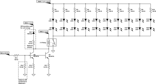
So this means you will string two LEDs (arranged so that they conduct in the same direction) and add one resistor, also in series. Three parts in such a series "string." Then you will do this 10 times, so that there are 30 parts together to make up 10 independent resistor+LED-pair strings. These strings have two ends and these ends are all connected so that you have 10 parallel strings. This makes up the entire "light system" -- itself appearing as just one component to the rest of the circuit.
Now, before I follow through with this line of thought, it's a good time to pause. This has been designed so that the worst case, per string, is \$18\:\text{mA}\$. But there are 10 strings. So we have to consider handling up to \$180\:\text{mA}\$ with either the relay (which can easily handle it) or with the BC547 (which cannot do so, by itself.)
Also, while the relay datasheet is sparse it suggests up to \$I_\text{COIL}=\frac{450\:\text{mW}}{3.0\:\text{V}}=150\:\text{mA}\$.
So it's almost like the phrase, "six of one, half-dozen of the other." Both the worst case coil current and the worst case total LED light's current are not far apart from each other. And, sadly, the BC547 just isn't designed for either of these currents.
Oh, well.
And still more. To saturate the BC547 so that it operates like a switch, the base current should be on the order of a tenth of the collector current that is being handled. Here, that's either \$15\:\text{mA}\$ or \$18\:\text{mA}\$ -- yet your I/O is rated (I read from you) at \$12\:\text{mA}\$.
But I think you'll be fine. The "tenth" rule isn't a law. And it is very likely the BC547 will saturate well enough at less base drive current. So I think that means we'll just "buy it" and assume that \$12\:\text{mA}\$ from the I/O pin will be sufficient.
There is another small issue -- what exactly is the voltage at the I/O pin when it is sourcing \$12\:\text{mA}\$? Since I don't have that information handy, I'm just going to assume that it is \$2.8\:\text{V}\$ and call it a day.
We still have to decide between the relay and directly driving the LEDs -- either case using at least two BJTs to get there. I'm just going to tell you to use the relay and switch the relay with the BJTs. Several reasons. One is that you have the relay and may want to learn by using it. Another is that it requires less current to operate and also it can switch \$1\:\text{A}\$, which is a lot more current and more useful if you later want to add more. And there is one final reason: trying to share current between two BJTs requires some voltage overhead at the emitter end in order to achieve it. And you don't have that much to play with, really, when using the BJTs to directly operate the LED strings.
Current sharing with BJTs means (usually) reserving out about \$500\:\text{mV}\$ for their emitter resistors. With \$75\:\text{mA}\$ for each BJT, this works out towards the standard value of \$6.8\:\Omega\$. The base hopefully will be nearer \$1.3\:\text{V}\$ (thereabouts), then. And if the I/O pin may droop to about \$2.8\:\text{V}\$, I computed the base resistor of \$120\:\Omega\$ as satisfactory.
Here's a suggestion for you, now:

simulate this circuit – Schematic created using CircuitLab
Yes, I added your \$10\:\text{k}\Omega\$ resistor!
A final note. Sacrificing some voltage at the BJT emitters means their collectors are also limited. However, since most relays engage at 70% I don't foresee a problem. The relay should engage with this circuit (and the BJTs should share the load to a fair degree.)


