0
\$\begingroup\$

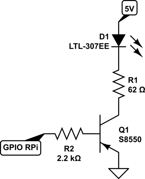
I am using a GPIO pin from the Raspberry Pi to control the Base of a PNP S8550 Transistor and turn an LED on and off. I designed the circuit below:

  • Base connects to GPIO from Raspberry Pi
  • Collector connects 5V to LED
  • Emitter to GND

schematic

simulate this circuit – Schematic created using CircuitLab

Yes the Resistor values are correct. I know I am overdriving the LED. LED is also brand new. I want to push 60mA through my LED but the output I am seeing is 3.5mA.

NOTE: CIRCUIT UPDATED

\$\endgroup\$
15
  • \$\begingroup\$ You should use an NPN transistor as a low-side switch, not a PNP transistor. \$\endgroup\$ Commented Nov 15, 2019 at 23:49
  • \$\begingroup\$ I don't understand. Why NPN? Is it not possible to use a PNP? I already bought PNP. Can we make this work? \$\endgroup\$
    – presish
    Commented Nov 15, 2019 at 23:51
  • 1
    \$\begingroup\$ Alternatively, you should use a PNP transistor as a high-side switch, not low-side. \$\endgroup\$
    – Hearth
    Commented Nov 15, 2019 at 23:52
  • \$\begingroup\$ What do you mean by high-side / low-side switch? never heard this terms \$\endgroup\$
    – presish
    Commented Nov 15, 2019 at 23:58
  • 1
    \$\begingroup\$ The arrows in the LED and the transistor point in the direction of conventional current flow. They point at each other in your circuit, indicating that something is wrong. \$\endgroup\$
    – JRE
    Commented Nov 16, 2019 at 0:15

3 Answers 3

2
\$\begingroup\$

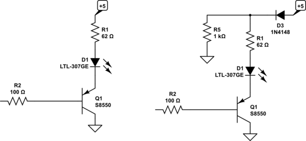
You are operating the transistor as an emitter-follower in reverse mode (it's not a good circuit, you should just buy an S8050, they're good to have around so get a few NPN and PNP). The beta is quite low so the Pi will try to sink a lot of current (on= low, by the way) and with it high @3.3V, it may not fully turn the LED off. As an emitter-follower, it will have no voltage gain (but it does have current gain). So the voltage at the emitter (collector grounded) will change from about 3.8V to about 0.8V when the input changes from 3.3V to 0V.

To make this work, swap emitter and collector on the transistor. To make it fully turn off (if that's a problem), add a diode as shown in the right hand circuit. This will be necessary if your LED is an IR (infrared) type, which your calculation of the 62 ohms seems to imply. You could also use two LEDs in series, which is a more efficient use of current (twice the light for the same current), again assuming infrared LEDs with a Vf in the roughly 1.2V range.

schematic

simulate this circuit – Schematic created using CircuitLab

R2 is not strictly necessary but it might (possibly) help save your Pi if you make a wiring mistake or the transistor becomes damaged.

Because the transistor is operating as an emitter follower and not a switch, the voltage drop across it will be more like 700mV than the 100mV you might get with a proper saturating switch (eg. S8050 as a low-side switch). Hence you will both have to adjust the value of R1 and to keep in mind that the dissipation of the transistor will be in the 350-400mW range at 60mA which means it will get rather hot if left on continuously (but acceptable for the TO-92 version, at moderate maximum ambient temperature and for something where reliability is less important than cost).

Consider the 62 ohm value as a placeholder, the actual value to get 60mA will be lower. It's possible to calculate it with proper datasheets, but of course you have not supplied that information.


Bottom line, the ideal circuit would use an S8050 as a saturating switch. There is little in the way of advantages to using an emitter follower and probably bit more danger of damaging your Pi from a bad connection. An S8050 is maybe 1/3000 of the cost of the Pi so your x̄ is lower if there is more than 0.000003% of a chance of such an error.

You could also add a new 3.3V regulator to the 5V supply and then you could use the S8550 as a saturating switch with emitter connected to the (new) 3.3V rail. Having no voltages in your circuit higher than 3.3V or lower than 0V makes it a lot harder to damage the Pi.

\$\endgroup\$
1
\$\begingroup\$

Not sure how you are getting the 3.5mA, but I can comment that this is a pretty weird driving arrangement. You should put the PNP up top, with the emitter at 5V and the collector attached to the LED.

Alternatively you could swap out the PNP for an NPN and drive it from the low side.

*** To be clear I find this weird because this really isn't a switch circuit, so it doesn't seem to be what you want.

\$\endgroup\$
7
  • 1
    \$\begingroup\$ The PNP at the top won't work properly, either. Raspberry Pi GPIO pins only go up to 3.3V. With the PNP up at the top, the LED will always light up. \$\endgroup\$
    – JRE
    Commented Nov 15, 2019 at 23:55
  • \$\begingroup\$ Do RPis have open-drain outputs? He could use that as a level-shift. \$\endgroup\$ Commented Nov 15, 2019 at 23:56
  • 2
    \$\begingroup\$ @ColinMarcus: even if the RPi has open collector outputs, it very probably won't want to see them pulled above 3.3 volts. \$\endgroup\$ Commented Nov 16, 2019 at 0:05
  • \$\begingroup\$ Please note the correct circuit is updated now (emitter to GND) \$\endgroup\$
    – presish
    Commented Nov 16, 2019 at 0:09
  • \$\begingroup\$ The Pi doesn't have an open drain option. It seems you can fake it, though. \$\endgroup\$
    – JRE
    Commented Nov 16, 2019 at 0:12
1
\$\begingroup\$

The RPi outputs are usually \$3.3\:\text{V}\$ and they probably can handle saturating your PNP as a switch. But the problem is the \$3.3\:\text{V}\$ limit (which assumes zero sourcing current.) The I/O pin can sink current when driven high, but that's not controllable as it is only through a protection diode -- which, in general, you should NOT rely on for these purposes.

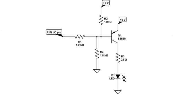
If you only have one S8550 BJT (and not two) then you can attempt something like this:
schematic

simulate this circuit – Schematic created using CircuitLab

You'll need to adjust \$R_3\$ to get the current you want in the LED. The value I've provided is a wild guess and probably should be larger than I've shown. So perhaps start with a larger value and work towards that one to get the current you want.

You may also need to adjust \$R_1\$. But here's the problem. This circuit relies upon the I/O pin protection diodes and attempts to limit their current to a value that is low enough to avoid latch-up. If you reduce \$R_1\$ in order to increase the base current (when actively driving the LED), then you take risks of too much protection diode current and therefore latch-up. I chose the value you see in order to limit the protection diode current to under \$1\:\text{mA}\$. Some MCUs can handle that. Some cannot. So there's nothing assured about this specific design. It's a risk. But it may be satisfactory, too. Just know that this isn't well-managed and that you may be taking some risks. But the pay-off is that it may work okay.

A final note about the above circuit. There still may be some LED light, even when turned off (I/O pin high.) That's because there's still a small amount of base current. I've tried to keep that base current to around \$1\:\mu\text{A}\$, so there shouldn't be much LED light. But in a dark situation, I can't promise you won't notice it. So, even assuming everything else appears to work out, it's still possible that you may see "some" emission from the LED when you've tried to turn it off.


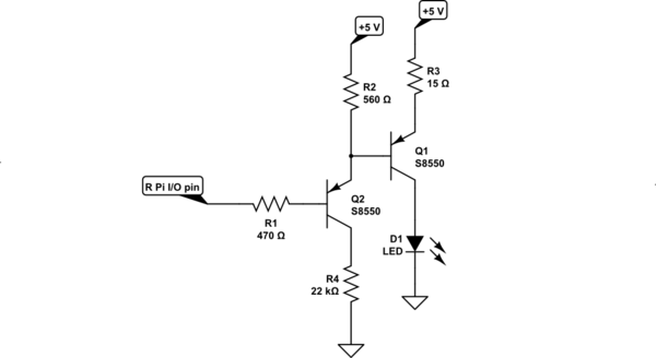
If you have two S8550's handy, then you can attempt the following:
schematic

simulate this circuit

Here \$Q_2\$ is operating as an emitter-follower and \$R_3\$ is used to regulate the current into the LED. I chose to assume about \$1\:\text{V}\$ across \$R_3\$. Given that, and assuming about \$V_{\text{BE}_1}\approx 800\:\text{mV}\$, this means we want about \$3.2\:\text{V}\$ at the base of \$Q_1\$ (when the LED is on.) There's a problem at this point -- I can't be sure that \$Q_1\$ is saturated. It may not be -- it depends on the LED's required voltage. Just to manage the situation, I decided that I want at least \$3\:\text{mA}\$ in \$R_2\$ (this will guarantee a certain range of emitter currents for \$Q_2\$), so I set \$R_2=\frac{5\:\text{V}-3.2\:\text{V}}{3\:\text{mA}}\approx 560\:\Omega\$. \$Q_2\$ will be saturated by design (\$R_4\$ will guarantee it) and I therefore expect about \$2.5\:\text{V}\$ at the base of \$Q_2\$. If I assume that \$Q_1\$'s base current will be around the same current I just set for \$R_2\$ (this assumes \$\beta_1\ge 20\$), this means I need to be able to sink \$6\:\text{mA}\$ (which the RPi I/O pin can achieve.) So \$R_1=\frac{2.5\:\text{V}}{6\:\text{mA}}\approx 470\:\Omega\$.

When the LED is off, the I/O pin is at \$3.3\:\text{V}\$ and I want the base at \$Q_1\$ to be at least \$4.5\:\text{V}\$, so that it is off, as well. This means the base of \$Q_2\$ will be about \$3.8\:\text{V}\$. So the base current in \$Q_2\$ now will be about \$1\:\text{mA}\$. About all of that current will be sourced by \$R_2\$ and that means only about \$560\:\text{mV}\$ across it. This does strongly suggest that \$Q_1\$ will be off, which is what's desired.

To keep \$Q_2\$ fully saturated in both cases and recognizing that there won't be much collector current for \$Q_2\$ in either situation, it's a good idea to make its collector resistor "large." Taking the LED *off case to heart, I'd want the collector resistor to be at least \$11\times\$ larger than \$R_2\$, but given my uncertainty about the saturation state of \$Q_1\$ that should be at least double it, again. So at least \$22\times\$ larger than \$R_2\$. I chose \$R_4=22\:\text{k}\Omega\$. You might be able to get by with less, but I'd prefer you didn't.

Now you can adjust \$R_3\$ to get the LED current you need. (The value I provided is just a guess and there are a number of factors, such as ambient and operating temperatures, that will influence your actual choice.)


I don't consider either one of these to be particularly good choices. Both may exhibit a very low level of LED current when turned off that may be visible in some circumstances. Both can be adjusted (for example, try \$R_2=470\:\Omega\$ in the 2nd circuit) to help that. But neither circuit is perfect.

It really is better if you pick up a few different types of transistors to help avoid being forced to use the wrong active devices thereby forcing some compromises in your goals.
\$\endgroup\$

Your Answer

By clicking “Post Your Answer”, you agree to our terms of service and acknowledge you have read our privacy policy.

Not the answer you're looking for? Browse other questions tagged or ask your own question.