I'm designing an adjustable high-voltage low-current power supply using UC3843 control chip.
Basic parameters: Uin = 24 V DC, Uout = 30-1000 V DC, Iout = 10 mA, Uripple < 1 V, fsw = 40 kHz
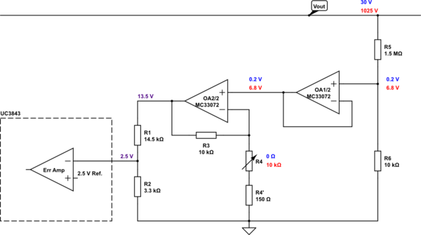
I have a few questions about one aspect of my desing - the voltage feedback. I most simple cases, the voltage feedback can be realized using a simple resistive divider, possibly with a variable resitor to achieve adjustable output voltage. However, in my case I can't use a potentiometer directly in the divider because of high voltage at the output. Instead of that, I came up with following circuit, which uses 2 op-amps, the first as voltage follower and the second, with variable gain, to achieve desired range of output voltage:

simulate this circuit – Schematic created using CircuitLab
(In blue are voltages with potentiometer set to low resistance, red is the opposite)
The IC operates in closed loop in order to achieve zero difference at the output of the error amplifier. That means, voltage between R1 and R2 will be in steady state equal to 2.5 V internal reference.
My questions are:
- Is there in general something wrong using an op-amp in voltage feedback like this? Are op-amps fast enough to transfer fast changes at the input to the output?
- Is op-amp MC33072 suitable for this application?
- Should I place some small capacitors for better noise imunity, e.g. across R6?

