0
\$\begingroup\$

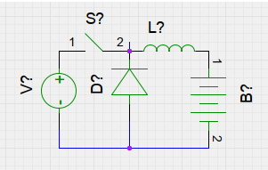
I have a very basic understanding of switched mode power supplies and know that this is a simple buck converter suitable to e.g. charge a 12 V car battery from an input of, say, 24 V, with a dc current that may have some ripple:

charger schematic

The voltage on the battery resp. the charging current can be controlled with the duty cycle on the switch.

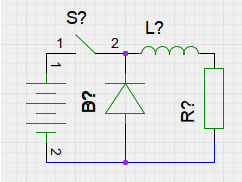
My problem is to find a similar schematic for discharging the battery with a controlled current. The purpose is to measure the discharge process in order to find the capacity of the battery. This is a schematic with the disadvantage that the discharge current goes on and off, instead of having just a little ripple:

discharger schematic

All I find on the Internet are schematics that regulate the output voltage / current over the resistor, but in my project I need to regulate the current in the battery instead, and want a dc current with just a little ripple.

Any ideas?

\$\endgroup\$
4
  • \$\begingroup\$ Do you want to build that thing in your mind yourself? Buy a DC DC converter if you are not an e engineer. \$\endgroup\$
    – GNZ
    Commented Dec 3, 2019 at 3:14
  • \$\begingroup\$ This is an unusual application because you want to keep the input current (relative to the DC/DC converter) constant, as opposed to output voltage or current. If the current level is not too high consider using a simple linear current source circuit as a load instead. \$\endgroup\$
    – joribama
    Commented Dec 3, 2019 at 3:16
  • \$\begingroup\$ You should be able to use the voltage across a sense resistor on the input side as the feedback voltage for the DC/DC converter. It may be a little tricky to figure out how much filtering you may need. \$\endgroup\$
    – joribama
    Commented Dec 3, 2019 at 3:26
  • \$\begingroup\$ @Genzo Why not building that myself? In my previous life I was an e-engineer :-) \$\endgroup\$
    – Roland
    Commented Dec 3, 2019 at 9:26

2 Answers 2

1
\$\begingroup\$

Use a boost circuit instead of buck then the battery current will be continuous

in a buck converter the curren draw is sufficient for the converter to enter continuous conduction mode, because the inductor is connected directly to the source, the source will also see continuous draw (with ripple at whatever level the inductor ripple is less any absorebed by input capacitance)

\$\endgroup\$
4
  • \$\begingroup\$ Care to elaborate? \$\endgroup\$
    – Voltage Spike
    Commented Dec 3, 2019 at 4:39
  • \$\begingroup\$ Excellent! I knew there should be an easy way. I just couldn't get it before you did. Thanks! \$\endgroup\$
    – Roland
    Commented Dec 3, 2019 at 9:35
  • \$\begingroup\$ @VoltageSpike en.wikipedia.org/wiki/Boost_converter \$\endgroup\$
    – Roland
    Commented Dec 3, 2019 at 9:35
  • \$\begingroup\$ Added advantage of a discharger with a boost converter is that I can charge another battery. Especially because I have to test a series of batteries. \$\endgroup\$
    – Roland
    Commented Dec 3, 2019 at 11:51
2
\$\begingroup\$

The main difference between charging and discharging is that during discharge you want to waste power. Therefore no matter what technique you use, you will need something to turn the power into heat.

The simplest way to do this is just switch in resistors in parallel until you get the desired current. However if the resistance is fixed you will need to log current or voltage periodically during the discharge. For finer adjustment you could PWM one of the resistors, perhaps with feedback to regulate the average current. Smoothing may not be required because the battery itself acts as a filter.

Another way to get constant discharge current is with a linear regulator. Set the output voltage to just below the minimum battery voltage minus regulator dropout voltage, and put resistance across the output to draw the desired current. The regulator only has to 'burn off' the voltage difference, so the load resistor(s) will absorb most of the power.

On the other hand you might want to reproduce operating conditions for a device that draws constant power (eg. a switching DC/DC converter). In that case you could simply use an off-the-shelf DC/DC converter with load resistors on the output.

To get constant input current to a switching converter you need to monitor the input current and use it to control the PWM ratio. A boost-mode converter draws continuous current, but it is not necessarily smooth

\$\endgroup\$
4
  • \$\begingroup\$ The point is not efficiency, altough I'd like to keep the dissipation in the R (e.g. a lamp) instead of in the transistor. The point is controllability, to me it seems easier to vary the switching frequency and duty cycle than to switch resistors on and off. \$\endgroup\$
    – Roland
    Commented Dec 3, 2019 at 9:29
  • \$\begingroup\$ The linear regulator is a good solution, +1, but since I already have the inductor for the charge circuit, I was looking to reuse that inductor for a switching solution for the discharge circuit. Also, I'd prefer a cheap lamp over a big cooling fin for a resistor or lin-regulator \$\endgroup\$
    – Roland
    Commented Dec 3, 2019 at 9:42
  • 1
    \$\begingroup\$ A lamp actually makes a good discharger because its resistance decreases at lower voltage, so it 'regulates' current somewhat better than a resistor, and you get an indicator for free! Probably best to use buck-mode switching to vary the current, as the output voltage can be turned down to zero. A boost mode converter's minimum output voltage is equal to the input voltage, so the lamp would have to be rated for a much higher voltage and its lower resistance at low voltage would work against you. \$\endgroup\$ Commented Dec 3, 2019 at 10:13
  • \$\begingroup\$ Although Jasen actually answered my question, you are probably right that it would be much simpler to build the discharger with just a lamp.Of course incandescant, not LED!!! If I select a suitable input voltage, even the charger would not need any additional regulation. A switch (transistor/fet) is only needed to automate the process with an arduino or raspberry pi, but "switch mode" current regulation is not really needed. \$\endgroup\$
    – Roland
    Commented Dec 3, 2019 at 11:42

Your Answer

By clicking “Post Your Answer”, you agree to our terms of service and acknowledge you have read our privacy policy.

Not the answer you're looking for? Browse other questions tagged or ask your own question.