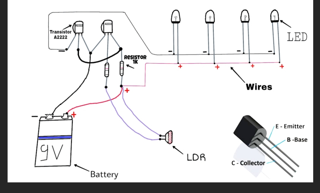
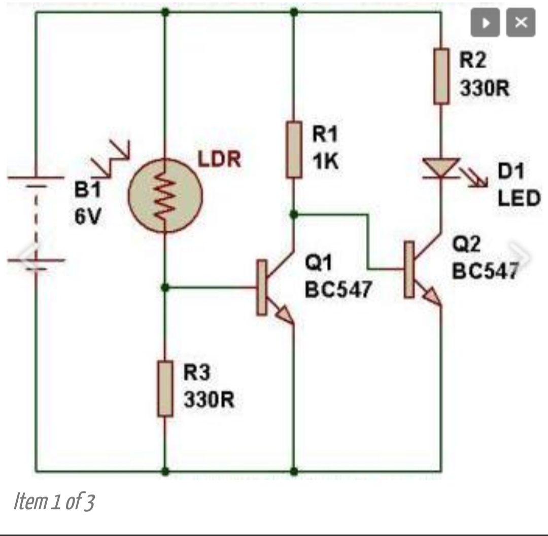
Could you please help me by checking whether this circuit diagram is correct for connection digram.
Kindly ignore resistor R2 330 R (as it is not included in the connection diagram)
Actually I am a beginner in the electronics.

Could you please help me by checking whether this circuit diagram is correct for connection digram.
Kindly ignore resistor R2 330 R (as it is not included in the connection diagram)
Actually I am a beginner in the electronics.

Ok,
First, I'm not exactly sure what your asking, but it sounds like the question is if the top diagram(connection) is an accurate rendition of the bottom diagram(schematic). Do I have that correct?
Second, even though I hate the stuff, I would recommend that at a minimum that you take a look at Fritzing.
Now for an answer.
No, the two barely have any correlation.
1. Why are you trying to run it at 9V instead of the requested 6V? That is only 4 batteries(AAA, AA, C or D) in series.
2. As constructed on the top diagram, you'll burn ALL of those LED's, at once.
3. Eeekkk..
For a better circuit that uses a 9V battery, check out this page, plus it only has ONE transistor and a good explanation.
The transistor Q1 is biased with the help of LDR and a known resistance. When the LDR has low resistance (day time), there is enough current into the base which enables beta*Ib current to flow into the collector. This current causes high drop in voltage across the resistor, leaving very less voltage for the second transistor's base.
Since the voltage at second base is not enough to allow current through, no current flows through the base and collector(ideally). So your LED can't get enough current to light up.
When LDR has high resistance, there is no current through 1st base and collector. So your 2nd base gets enough voltage to allow enough current to pass through it and causes higher current to pass through the collector. So your LED can light up.