0
\$\begingroup\$

I'm testing out the comparator LM393 but when I try and the comparator conditions meet it only outputs low and won't switch high.

That or I don't understand how it works properly so if you can help me out it would be great.

I have 2 power supplies (each independent.)

One output a voltage of 12V, the second can output 10V or 13V.

Output 1 would resemble Vref (12v)

Output 2 would resemble Vin (10-13V)

In the picture below

  • Vin is connected to the non-inverting input
  • Vref is connected to the inverting input
  • GND is connected for both supplies
  • resistors are for current limiting

The first diagram I've connected the led so when the comparator output switches low.

When only Vin > Vref it would light up.


In the second diagram I've connected the led so when the comparator switches high the LED will turn on

BUT no matter what the output won't switch high and the LED won't turn on. What am I missing here?

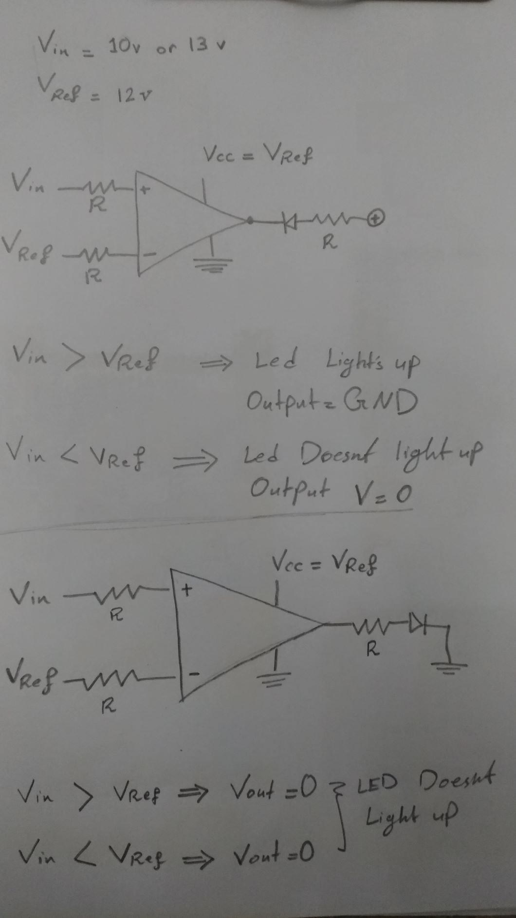
enter image description here

\$\endgroup\$
1
  • 2
    \$\begingroup\$ There ARE comparators that will pull high (as well as low). LM393 is NOT one of them - it only pulls low at its output pin. \$\endgroup\$
    – glen_geek
    Commented Jan 3, 2020 at 21:11

3 Answers 3

5
\$\begingroup\$

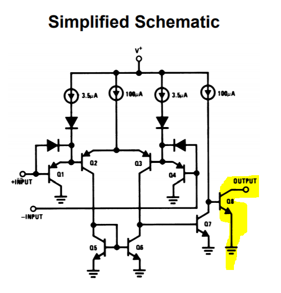
The LM393 has what's called an open collector output, as shown here from the datasheet.

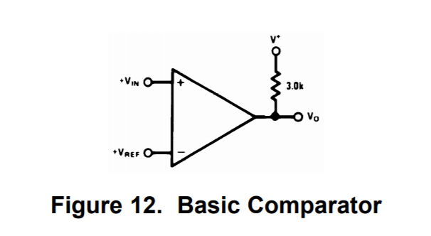
This means the output can be pulled LOW when the BJT is turned on, but requires an external pull-up resistor to go HIGH when the BJT is turned off.

enter image description here

The typical applications section shows this pull up resistor:

enter image description here

Because of this, I recommend using your first circuit implementation.

Let me know if you have any follow up questions!

\$\endgroup\$
2
\$\begingroup\$

You need a supply voltage that is higher than Vref by a couple volts. At 25°C, 1.5V is just enough to guarantee operation. From the datasheet:

enter image description here

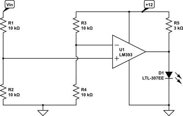
You can make it work by adding voltage dividers on each input, say equal value to R so that you get ~6V on each input.

Also note that the output is open-collector so your top circuit will work (with dividers), but for the bottom one use something like this:

schematic

simulate this circuit – Schematic created using CircuitLab

\$\endgroup\$
4
  • \$\begingroup\$ isnt it supposed to be sensitive as 0.1V difference ? \$\endgroup\$
    – amd moual
    Commented Jan 3, 2020 at 19:50
  • \$\begingroup\$ ok i will try that thank you very much \$\endgroup\$
    – amd moual
    Commented Jan 3, 2020 at 19:51
  • \$\begingroup\$ You must keep the voltage at the inputs within the range 0V to V+-1.5V for it to work properly. That's what "Input Common Mode Voltage Range" means. \$\endgroup\$ Commented Jan 3, 2020 at 19:52
  • \$\begingroup\$ While it is important to observe the input common mode range, that typically just results in non-linear performance. It would not cause the problem AMD is seeing here. @amdmoual, the comparator you have selected cannot output HIGH on it's own. It has an open collector output that can only go LOW. To output HIGH, there has to be an external pull up resistor on the output pin. \$\endgroup\$
    – TI_Lover
    Commented Jan 3, 2020 at 20:04
2
\$\begingroup\$

Always observe IC specs for Input and Output range. Comparators are often open collector output so you swap inputs and use active low.

Other Design details.

When making a lead acid 12V battery voltage OK indicator , you want to start with specs.

e.g. Consider a threshold of 12V and a tolerance +/-5% or below.

12.5 100% SoC (after quick load or settling time)
12.0V = 50% SoC
11.5V = 0% SoC

SoC= State of Charge

Then you need a diode or voltage reference that can give you 1% accuracy which might be hard so you can consider any diode, even an LED or precision Zener or LDO.

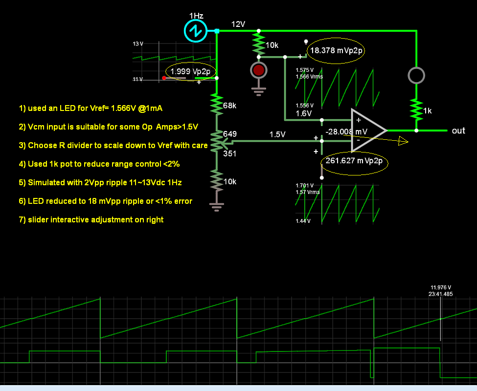
Here is one way using the same LED to scale down with a pot to adjust over the desire range only.

1) used an LED for Vref= 1.566V @1mA

2) Vcm input is suitable for some Op Amps>1.5V

3) Choose R divider to scale down to Vref with care

4) Used 1k pot to reduce range control <2%

5) Simulated with 2Vpp ripple 11~13Vdc 1Hz

6) LED reduced to 18 mVpp ripple or <1% error

7) slider interactive adjustment on right

enter image description here

\$\endgroup\$

Your Answer

By clicking “Post Your Answer”, you agree to our terms of service and acknowledge you have read our privacy policy.

Not the answer you're looking for? Browse other questions tagged or ask your own question.