2
\$\begingroup\$

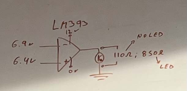
In LM393 datasheet it’s connected to GND on LOW, and disconnected of everything on HIGH. But on my tester I see on LOW: 100 Ohm when no load’s GND connected to Out pin. (No load at all). 850 Ohm when 12V led’d GND lead connected to LM393 out pin.

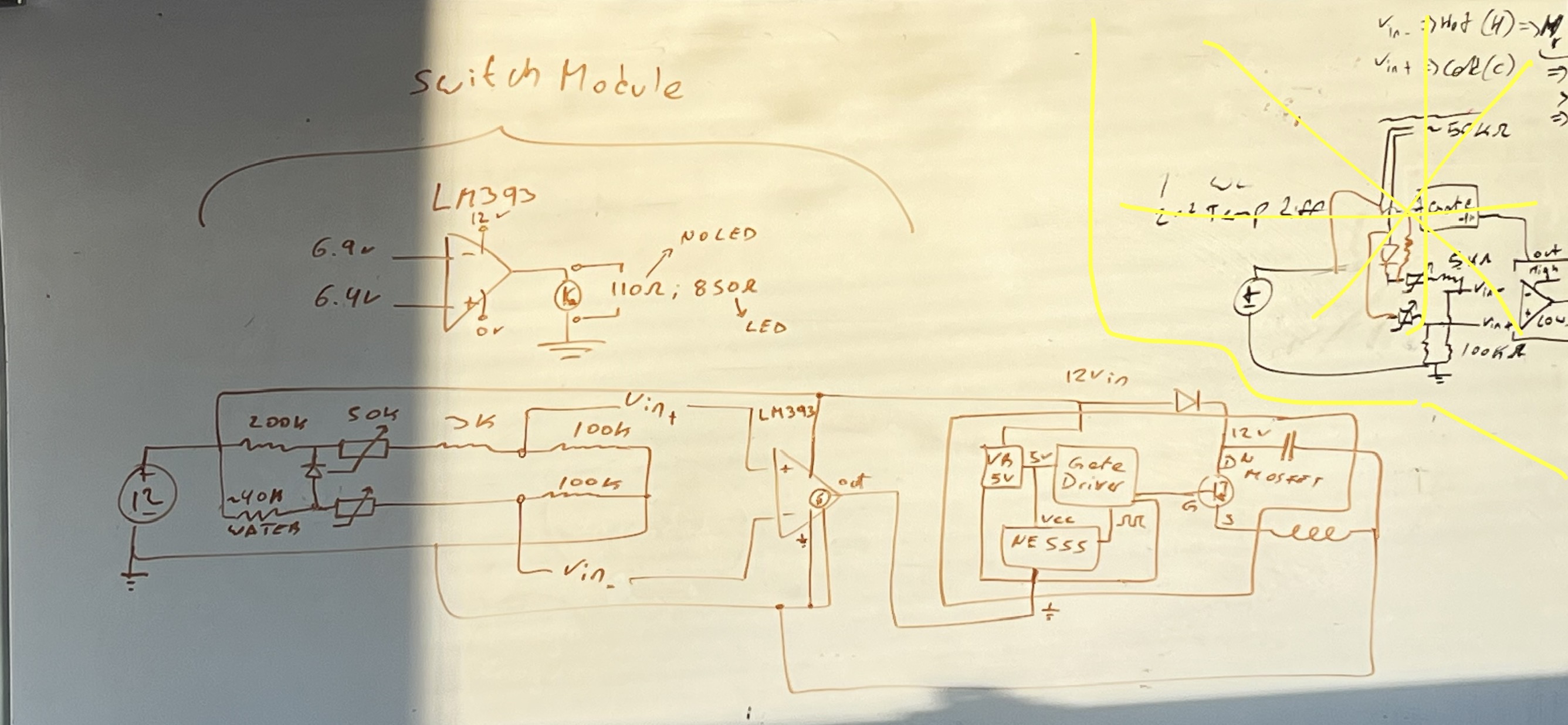
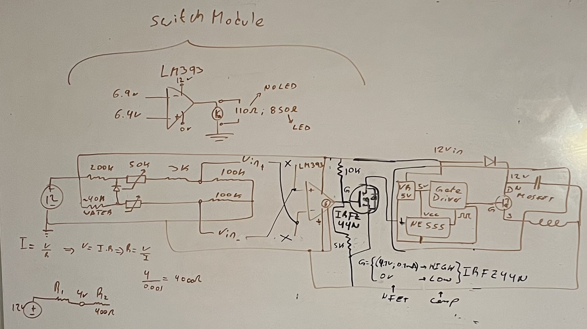
When I connect the GND of my (comparator-gated) PCB to the out pin nothing 12V fires up, only some 5V leds light up

Why? I expected zero Ohm on LOW. LM393 usage: enter image description here Big picture: enter image description here Fix (black): enter image description here Edit: @justme, I had to use the comparator as a gate driver, was forced to invert the inputs as the MOSFET was always on in the original setup. Driving the gate with 4V; 0.1mA Thanks for the help!
\$\endgroup\$
6
  • 1
    \$\begingroup\$ Is ground connected to negative supply? Polarity of ohmmeter reversed? I wouldn't call 100 ohm high in the context of an open-collector IC output. \$\endgroup\$
    – tobalt
    Commented Nov 29, 2023 at 20:38
  • \$\begingroup\$ What tester you used? A multimeter? How you tested? In ohms mode? How much load is your PCB in amps? Why do you expect the LM393 output to be a 0 ohm superconductor to GND? \$\endgroup\$
    – Justme
    Commented Nov 29, 2023 at 20:54
  • \$\begingroup\$ @justme regular multimeter in Ohms mode. (The ones that beep bellow a threshold ). My PCB is 0.2Amps with fan on. As LOW is GND connection I set things up to GND thru out pin. Thus I expect low Ohm. \$\endgroup\$
    – juanmf
    Commented Nov 29, 2023 at 21:09
  • \$\begingroup\$ Edited with full circuitry. \$\endgroup\$
    – juanmf
    Commented Nov 29, 2023 at 21:11
  • 1
    \$\begingroup\$ @juanmf Thanks, very good description, everything required for an answer is there. \$\endgroup\$
    – Justme
    Commented Nov 29, 2023 at 21:20

2 Answers 2

3
\$\begingroup\$

You can't test the output of a LM393 with an ohmmeter.

Or you can, but the results are meaningless, because, the path between LM393 output and ground is not a resistance.

So you get an incorrect measurement because you told your multimeter to measure a resistance but you did not give it a resistance to measure.

You are also trying to power a circuit through the LM393 output. It's not strong enough for that.

When the output drives a 4mA load, the output is guaranteed to be below 0.7V over full temperature range, typically 0.13V and max 0.4V at room temperature. If the voltage is allowed to rise up to 1.5V, it is guaranteed to pull at least 6mA.

The maximum allowed current before it damages is 20mA. It cannot drive your 200mA load.

So yes, the output is not a resistor and not 0 ohm short circuit. You can't measure it with multimeter in resistance mode for meaningful reasults. It's not a power relay intended to drive loads directly.

\$\endgroup\$
3
  • \$\begingroup\$ Added full assembly diagram, I’m not powering the PCB with the LM393. Just providing path to GND. — edit: my bad. I see what u mean. So I need the LM393 to drive a MOSFET instead? \$\endgroup\$
    – juanmf
    Commented Nov 29, 2023 at 21:41
  • \$\begingroup\$ @juanmf You can use the weak open-collector output logic signal from the LM393 to do anything you want, like drive a transistor to switch loads or relays. \$\endgroup\$
    – Justme
    Commented Nov 29, 2023 at 22:44
  • \$\begingroup\$ I’ll test this, in essence same content as the other response, but more personalized to my mistakes, so unless better ideas I’ll mark this one as accepted answer as soon as I can get bat to the breadboard. \$\endgroup\$
    – juanmf
    Commented Nov 29, 2023 at 23:15
3
\$\begingroup\$

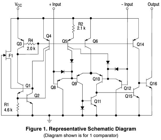
Here is the schematic from the datasheet:

https://www.onsemi.com/download/data-sheet/pdf/lm393-d.pdf

As you can see, the transistor Q16 is between the output and ground and is responsible for pulling the output low.

This is typical for comparators, and is called an "open collector output". Often you want to use this to drive a transistor which will operate your load, rather than directly.

I'm not sure what the saturation voltage (collector to emitter) is for Q16, but it is not zero.

Once you realize this isn't really ohmic and take that into account, I think it will become clear for you.

Please also notice the maximum current you can draw, as you are attempting to exceed it.

\$\endgroup\$
0

Your Answer

By clicking “Post Your Answer”, you agree to our terms of service and acknowledge you have read our privacy policy.

Not the answer you're looking for? Browse other questions tagged or ask your own question.