1
\$\begingroup\$

This questions is kind of related to this:

Prevent oscilloscope scrolling

However, now I have a decent signal generator (well still budget, but for my needs more than enough, FeelElec FY6900, 60 MHz signal generator).

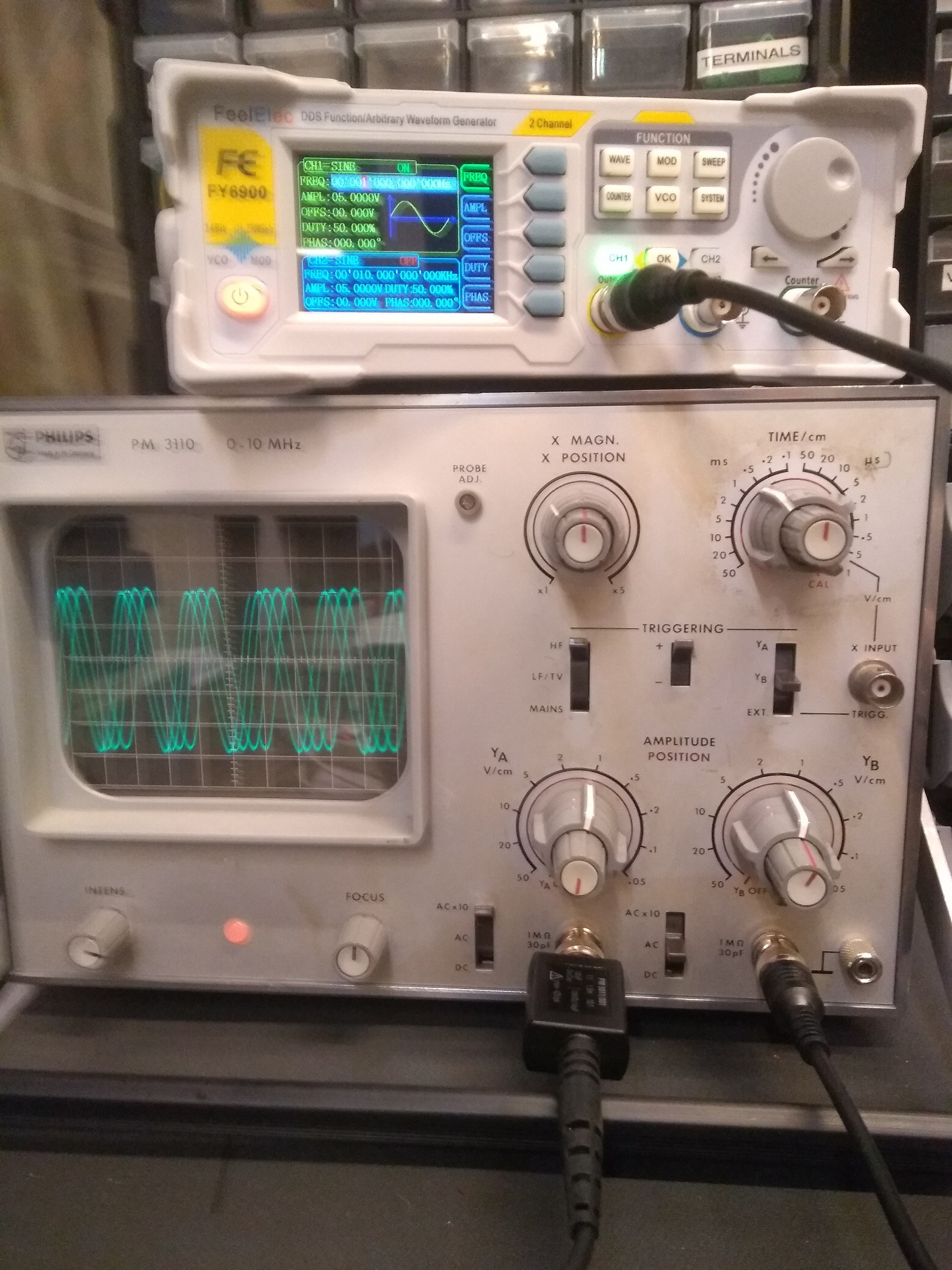
And two oscilloscope (one I will not mention in this question, but in a next one). The one I want to use for now is a 10 MHz Philips PM3110 , 10 MHz dual channel scope).

I use a sine signal. At 10 MHz, I get a very nice steady (non scrolling) signal at the oscilloscope using the time (x coordinate) of .5 us/square.

However, when I move down the signal generator to 1 MHz, at any possible x coodinate setting, the display scrolls faster or slower. The only way to make it kind of fixed is to change the inner x-coordinate knob, however, that changes the reading (the width of the signal over the squares, so it's not really useful).

I set the trigger to the correct channel, to LF, and high edge triggering, but actually, it doesn't change a thing.

What am I doing wrong?

(note from the oscilloscope, only the right cable is connected, channel B).

enter image description here

Conclusion (see chat for more info)

The PM3110 oscilloscope's trigger switches do not seem to work well, but the most important is that tapping the side of the case causes (in almost all instances) the beam to be steady, so the encoders/contacts are not conducting well.

Besides fixing (see accepted answer: cleaning/changing caps), some tips (also see chat):

  • Use another oscilloscope (found out my old PM3253 is working better than expected)
  • Redirect the output of the signal generator as trigger input for the PM3110.
  • Change HF/LF (because of video signals there is a 17 KHz switch). I noticed sometimes I have to increase the intensity of the beam to make it visible.
  • Change trigger level (PM3110 does not have one).
\$\endgroup\$
4
  • 1
    \$\begingroup\$ Comments are not for extended discussion; this conversation has been moved to chat. Any conclusions reached should be edited back into the question and/or any answer(s). \$\endgroup\$
    – Dave Tweed
    Commented Jan 4, 2020 at 11:49
  • \$\begingroup\$ @DaveTweed Thanks (Sometimes I see the option to move it to a chat, sometimes not; this time not; and I cannot even add comments to the chat. \$\endgroup\$ Commented Jan 4, 2020 at 14:55
  • 1
    \$\begingroup\$ All the permissions look correct to me, so I've raised the issue on Meta: Question owner can't write in chat created from comments - system picked wrong “Michel Keijzers”?. We'll have to wait and see what happens. \$\endgroup\$
    – Dave Tweed
    Commented Jan 4, 2020 at 16:59
  • \$\begingroup\$ @DaveTweed Thanks ... it seems to be fixed now (I will not send more comments here to prevent another comment burst; thanks for the help). \$\endgroup\$ Commented Jan 4, 2020 at 17:07

1 Answer 1

2
\$\begingroup\$

Trigger circuit works OK @ 10 MHz but doesn't quite work at lower frequencies.

This kind of fault is very often due to degraded electrolytic capacitors in such old equipment. Many fixes have been accomplished with a scattergun approach: replace every electrolytic capacitor in the trigger signal chain.

Or you can start with C501, C502, C503, C508 in Unit 3 PCB where trigger signals are processed. Probably safer to replace any/all you see.

\$\endgroup\$
5
  • 1
    \$\begingroup\$ Thanks for this information. Actually ... I found the problem, it mostly is present indeed at lower frequences (below 100 KHz). When I turn down the X position (smaller time per square), and gradually increase it, I either see scrolling or multiple 'beams' on the screen. The fix is: gently tap against the right side of the box... not very 'technical' or a sound solution, but it works ... can you maybe confirm if this might be related to your solution? (changing capacitors?) \$\endgroup\$ Commented Jan 4, 2020 at 0:44
  • 3
    \$\begingroup\$ Not likely related. Tapping fix suggests switch contacts need cleaning. Sometimes they come back with exercise - wiping away oxides/crud. There are a lot of switch wafers in there, some of which are activated at lower frequencies. Another tapping symptom is potentiometer wipers making intermittent contact. Many 'scopes are abandoned for reasons of intermittents like this. \$\endgroup\$
    – glen_geek
    Commented Jan 4, 2020 at 0:56
  • \$\begingroup\$ Thanks ... I think I will start cleaning the contacts (I assume you mean the contacts on the outside)? ... because I don't feel too confident to try to repair it before it's really broken :-) \$\endgroup\$ Commented Jan 4, 2020 at 0:58
  • 3
    \$\begingroup\$ Switch contacts inside, particularly those involving the 3 front-panel triggering. There are also rotary switch wafers on the huge TIME/cm rotary involved too. Don't be intimidated - these can be attacked with a spray of contact cleaner (with a small dia. nozzle extension tube). Spray with power off (collecting drippings), then exercise. \$\endgroup\$
    – glen_geek
    Commented Jan 4, 2020 at 6:06
  • \$\begingroup\$ Thanks for the clarification. btw, I'm not intimidated about spraying, but (slightly) resoldering all caps. \$\endgroup\$ Commented Jan 4, 2020 at 14:54

Your Answer

By clicking “Post Your Answer”, you agree to our terms of service and acknowledge you have read our privacy policy.

Not the answer you're looking for? Browse other questions tagged or ask your own question.