0
\$\begingroup\$

I have a circuit that consists of an Arduino controlling a small PAM8403 based amplifier which is powered via an L7805CV voltage regulator. When I press a button the arduino sends an audio signal to the amp and switches on a SPST relay. The whole thing is powered by four AA Energizer Lithium batteries supplying about 6.65V.

Without anything connected to the relay (except the signal and GND pins) this circuit draws about 0.22A. However, I want the relay to switch on a small motor and heating coil that I connect to the same battery pack as all the other stuff, so that the motor and coil get powered on when the button is pressed.

However, when I press the button, the amplifier cuts out and the circuit behaves erratically. The motor and coil run fine, however.

If I connect the motor and coil to the same battery pack, I measure a current of roughly 1.5A. This seems well within the range of what the batteries can supply according to the datasheet.

What am I missing here? I don't see why the rest of the circuit is affected by a load that should be well within the power supply's limits.

\$\endgroup\$
3
  • \$\begingroup\$ Which motor? How much current does the motor alone draw, and what is it powering? \$\endgroup\$ Commented Jan 27, 2020 at 23:09
  • \$\begingroup\$ This may be noise/EMF from the motor and/or coil. Look up "flyback diode" and "relay snubber" and see if you need these things. \$\endgroup\$
    – bitsmack
    Commented Jan 27, 2020 at 23:20
  • \$\begingroup\$ Are you powering the relay using the ardino or are you using a transistor with direct 6V supply? If you're powering a relay using a GPIO on the arduino, you'll probably be over load for the 7805. \$\endgroup\$
    – Natsu Kage
    Commented Jan 27, 2020 at 23:38

1 Answer 1

4
\$\begingroup\$

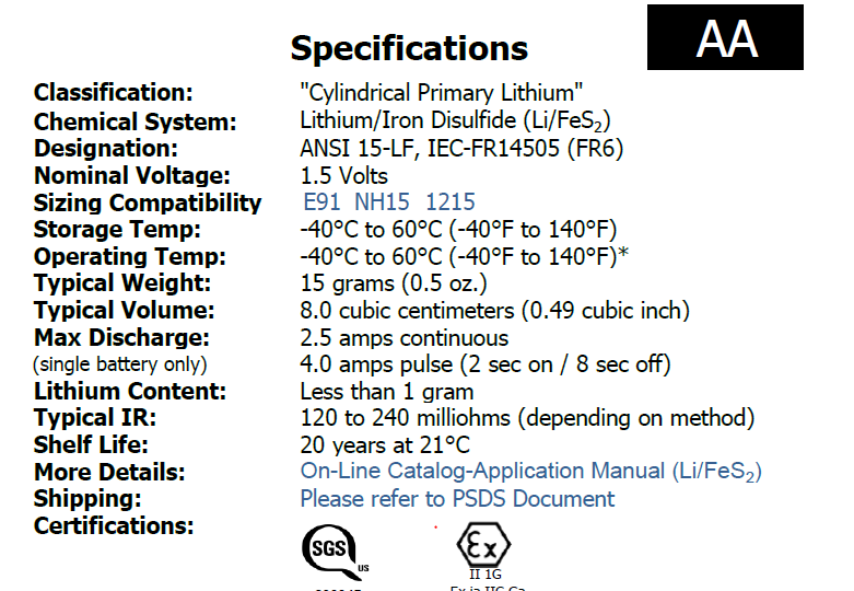
Your motor is a lot less sensitive to voltage than your circuit is. You are probably looking at this: enter image description here

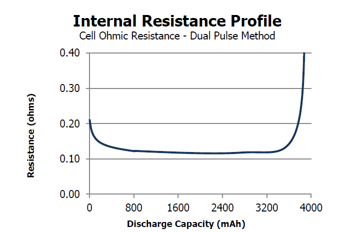
But front-page "advertising" numbers can't be trusted, especially for numbers with more complicated behaviour. You should be looking deeper in the datasheet at this: enter image description here

Your battery's internal resistance is 0.12Ohms, at best. At 1.5A you lose 0.18V per cell. If your nominal voltage is 1.5V per cell, then you are 5.28V.

If your battery is brand new, the internal resistance is 0.2Ohms and you have 4.8V when drawing 1.5A if using the nominal voltage. But your brand new battery probably starts at a high enough voltage to counteract this and more so your initial voltage is higher than nominal rather than lower.

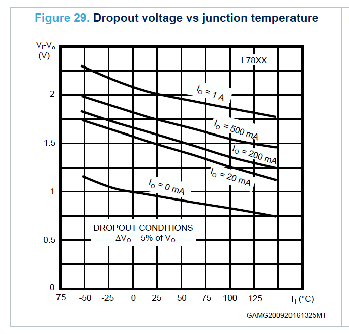
Your LM7805 has needs a headroom (has a dropout voltage) of 2V on top of its output to operate when supplying 1A. You are drawing less current than that so the dropout voltage is less but you are still probably operating the regulator in a region where it's just struggling to pass all the input voltage straight to the output but it's a regulator, not a switch so even more voltage is dropped in that process as well.

According to the datasheet of the LM7805CV manufactured by ST at 220mA, the dropout is ~1.6V. enter image description here

\$\endgroup\$
8
  • \$\begingroup\$ I think I follow, although I don't quite get your math, although you may have been rounding off. If the internal resistance is 0.12Ohms, wouldn't I lose 1.5 * 0.12 = 0.18V per cell? And if my nominal voltage is 4*1.5V, wouldn't that mean 6V - 0.18V * 4 = 5.28? \$\endgroup\$
    – Bas
    Commented Jan 27, 2020 at 23:11
  • \$\begingroup\$ @Bas I initially used 0.100Ohms but went back to use 0.120Ohms but missed a spot. \$\endgroup\$
    – DKNguyen
    Commented Jan 27, 2020 at 23:12
  • 1
    \$\begingroup\$ @Bas I just added in a blurb to try and cover that. The headroom required tends to increase as current demand increases. When you draw less current, the dropout is lower. But if you are operating below the dropout, the regulator will either shut down by design, or attempt to pass everything it can from the input to the output but voltage is lost in the process. \$\endgroup\$
    – DKNguyen
    Commented Jan 27, 2020 at 23:18
  • 1
    \$\begingroup\$ @Bas Never use a resistor. Resistors will drop voltage relative to the current passing through them causing the output voltage to vary with load which will muck up the works. The whole point of a regulator is that it drops whatever voltage is required to keep the output voltage constant, regardless of current. I would just add another series battery to be honest as long as it doesn't harm anything which it doesn't sound like it will, though you could find a lower dropout regulator. \$\endgroup\$
    – DKNguyen
    Commented Jan 27, 2020 at 23:22
  • 1
    \$\begingroup\$ @Bas No. For linear regulators, current in = current out. They regulate by burning off excess voltage as heat, not by converting "excess input" voltage in output current so that input current is less than output current. Switching regulators do this, which is why they are more efficient but are overkill and you shouldn't be using regulators for things like motors anyways. No way around it I'm afraid. You either need to provide more voltage or reduce the dropout voltage. \$\endgroup\$
    – DKNguyen
    Commented Jan 27, 2020 at 23:37

Your Answer

By clicking “Post Your Answer”, you agree to our terms of service and acknowledge you have read our privacy policy.

Not the answer you're looking for? Browse other questions tagged or ask your own question.