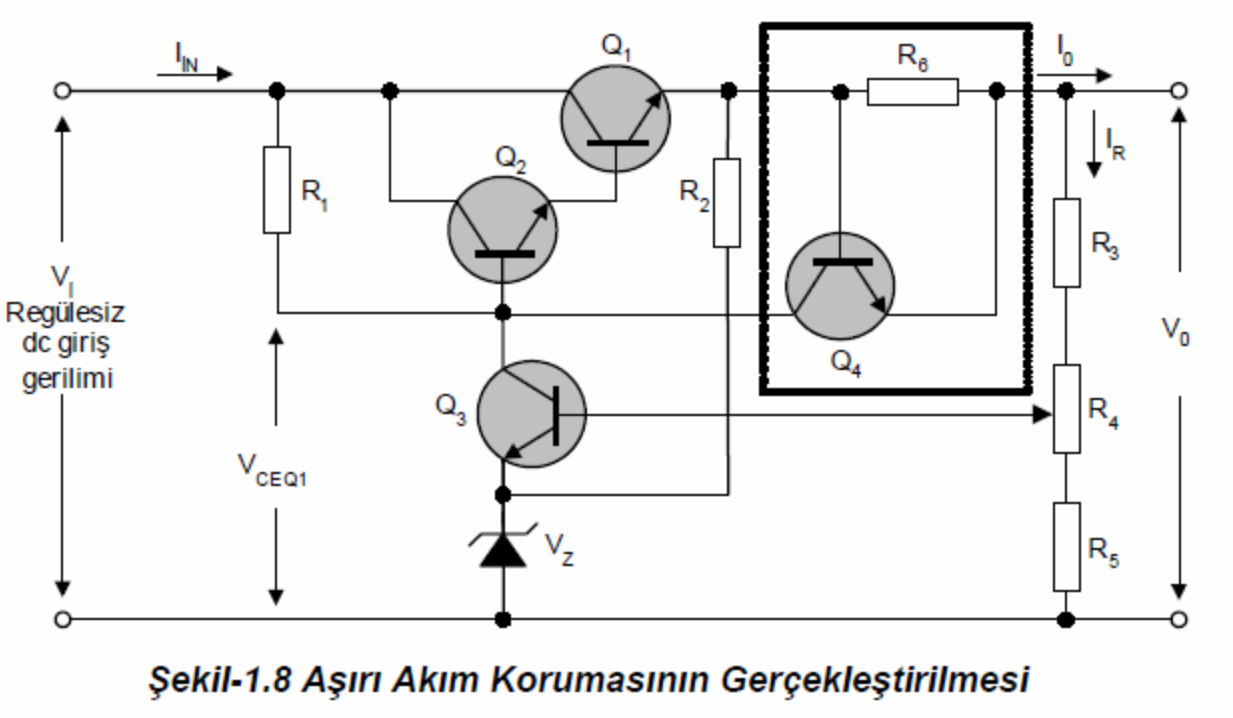
I found an over-current protection schematic, but I am confused about how the base of the Q3 is wired. Is it connected to a potentiometer? If so, to what terminal?
-
1\$\begingroup\$ Yes : the wiper. (It's a pretty bad circuit : if the wiper goes open circuit, trace out what happens! If the load doesn't like over-voltage... BOOM! Add a resistor between the wiper and the top of the pot, about the same value as the pot. \$\endgroup\$– user16324Commented Feb 29, 2020 at 22:42
-
1\$\begingroup\$ Looks like Q3 is part of an over-voltage protection function. By adjusting R4, the exact point at which it switches to over-voltage protection can be varied. At least that is how it looks upon casual inspection. \$\endgroup\$– user57037Commented Feb 29, 2020 at 22:44
-
\$\begingroup\$ If I were to model R4 as a resistor, where should I connect the base of Q3? I am not really looking to use a potentiometer on my circuit. \$\endgroup\$– HectorCommented Feb 29, 2020 at 22:48
-
\$\begingroup\$ That's a different question. Just tie R3,R5 and Q3b together and remove the pot. \$\endgroup\$– user16324Commented Feb 29, 2020 at 23:42
3 Answers
The base of Q3 is connected to the wiper terminal of potentiometer R4.
On schematics, potentiometers are normally drawn as a resistor with an arrow representing the wiper drawn at right angles to the resistor.
-
\$\begingroup\$ If I were to model R4 as a resistor, where should I connect the base of Q3? I am not really looking to use a potentiometer on my circuit. \$\endgroup\$– HectorCommented Feb 29, 2020 at 22:50
-
1\$\begingroup\$ You could model R4 as two resistors in series, with Q3 base connected to the junction of the two resistors. In this circuit, you could simply omit R4, and connect the bottom lead of R3 to the top lead of R5, and to the base of Q3. \$\endgroup\$ Commented Feb 29, 2020 at 22:56
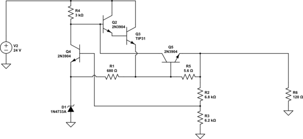
This is a voltage regulator with current limiting. Here are some typical values with current limited to a bit over 100mA and regulating from 24v down to about 12V. R6 represents the load.
R2/R3 in my schematic replace the pot. In general you usually model a pot as two resistors with the total equal to the element resistance (ignoring the usually small wiper resistance). So if the pot element is R ohms you have one resistor \$\alpha \cdot R\$ and the other resistor \$(1-\alpha \cdot R)\$ where 0\$\le \alpha\ \le 1\$ is the pot rotation as a fraction of the full electrical travel.
If you don't actually need a pot, the two resistors can just be absorbed into the series resistors R2/R3 in my circuit.

simulate this circuit – Schematic created using CircuitLab
You have dug up an ancient circuit; something that would have been used sixty years ago. It works tolerably as a regulator ( assuming you have low performance requirements ), but there is a serious error in the current limit section. Connecting Q4 straight to the current sense resistor will allow unlimited current to flow into Q4 and it will be destroyed before Q1 and Q2 turn off. A resistor should be put in series with the base, about 1K. You can get Darlington transistors that would have Q1 and Q2 in one package. Q1 should have a low value resistor (100 ohms) connected from base to emitter. A 6.2V zener is ideal here because it has a positive temperature coefficient that nearly cancels the negative coefficient of Q3. For a stable output a capacitor needs to be connected across the output.

