1
\$\begingroup\$

The following circuit is part of an electronic drum kit, and is repeated several times on the board to connect piezo elements to a micro-controller that samples the various inputs. I've represented the piezo sensor as an AC voltage source in the diagram.

updated circuit

I'd appreciate your help in understanding what's happening in this circuit, and what the responsibilities of the different components are. Below is few guesses as to what I think is going on, but I'd really appreciate some clarification on the intended functionality and how it's achieved.

  • C1

    This seems to do AC coupling of the input to the rest of the circuit. For this application, only changes in pressure are relevant, so I guess that makes sense if that's what its sole purpose is. Maybe it's serving another function, too?

  • D1

    I believe this is to keep the signal towards the MCU from going too far below 0V for the negative part of the input waveform, while leaving the positive half unaffected. Presumably that's to avoid damage to the MCU.

  • R1

    I'm unsure what this does. Is it just limiting current? Is it there to match impedance with something? Is it perhaps forming a filter with some of the other components?

  • R2

    I think this is a pull-down resistor, but maybe it's also part of some filter in combination with other components?

  • C2

    This looked to me like it's supposed to smooth the output, but I'm not sure about it. It seems like in an application like this you'd want crisp edges to detect on the micro-controller. I guess it's part of some kind of filter?

That's my wild guesses on this circuit so far. Your corrections would be much appreciated, as would links to sources that'd help me figure questions like these out on my own in the future.

Thanks!

Extra information as per previous responses:

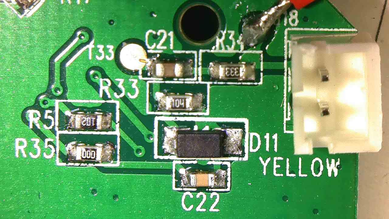
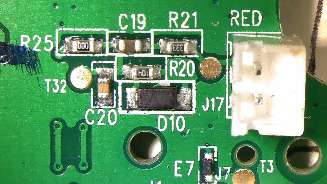
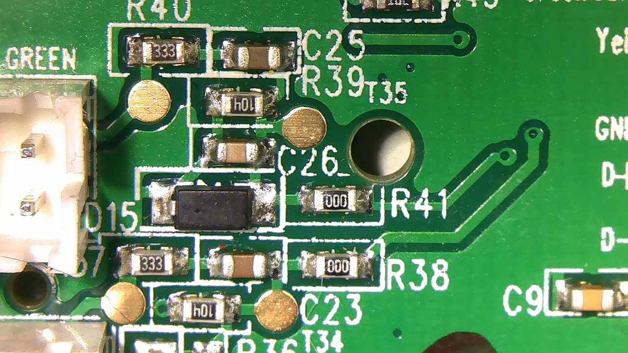
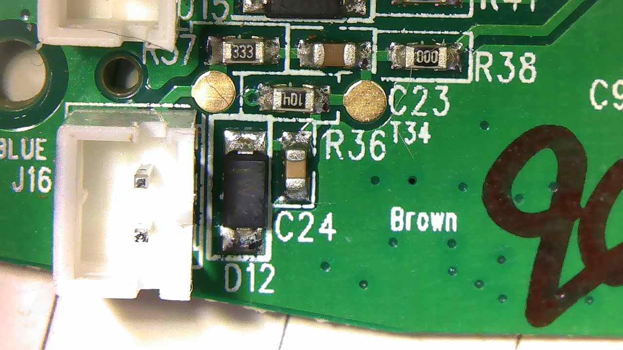
Here's pictures of the 4 instances of this circuit on the board I'm working with. The pin headers shown go off to the piezo sensors, and the vias after the zero ohm resistors are connected to micro-controller input pins.

y r g b

Also please note that the capacitor values were quite off in my original question with 1mF for C1 and 100 pF for C2, which many of you pointed out as wrong. I've since removed both capacitors from the circuit for measuring, and have updated the capacitor values accordingly.

\$\endgroup\$
12
  • \$\begingroup\$ Is C1 1 mF = 1 milli-farad = 1000 microfarad, or 1 uF = 1 microfarad? Presumably the latter. \$\endgroup\$
    – Russell McMahon
    Commented Mar 6, 2020 at 0:47
  • \$\begingroup\$ Your analysis seems "close enough". Often circuits are derived with some or all trial and error and then reused because they work. The 33k and 1 uF have a time constant of T=RC = 33000 x 1/1000000 = 33 ms. It MAY be designed as a high pass filter or "just works". The 100k loads it somewhat and forms a divider. Main use of 100k is to provide ground reference to output and discharge C2. C2 and 100k have time constant of about 10 us so C2 removes some of the VERY high frequency signal - but hardly noticeably. ... \$\endgroup\$
    – Russell McMahon
    Commented Mar 6, 2020 at 1:08
  • \$\begingroup\$ ... As you say, D1 clips negative swings of signal so you get a series of fast hardly shaped positive peaks from the piezo. || If you wanted more like a strike envelope increasing C2 adding a diode that charges C2 on the +ve peaks, moving D1 to the left so it clipped -ve peaks but passed +ve via D2 with R2 still discharging C2 would work. | But, apparently, it works as is. \$\endgroup\$
    – Russell McMahon
    Commented Mar 6, 2020 at 1:11
  • \$\begingroup\$ @RussellMcMahon I got that value from measuring C1 in circuit, and getting about 950 or so uF, which I've rounded up. With there being no other parallel capacitance of significance I can see, I think that's an OK measurement to make. Maybe I should've removed it from the circuit instead? I tried to measure C2 using the same technique, but with my measurement device bottoming out at 1uF, so I assumed C2 would be somewhere in the 10s to 100s of pFs. \$\endgroup\$ Commented Mar 6, 2020 at 1:47
  • \$\begingroup\$ I would exppect a capacitor that large to have it wrtitten on it. (meaning I suspect that it is not that large)_ can you add a photo? also 100pf seems small. \$\endgroup\$ Commented Mar 6, 2020 at 2:27

2 Answers 2

1
\$\begingroup\$

R1C2 is a low pass filter T=3.3us doesn't do much except AM-RF
R2C2 is a peak decay time T=10us
D1 is a negative clamp or +ve unipolar circuit to + rectify stick burst input to make a + pulse.

C1 is the wrong value and probably useless. Maybe 1nf

\$\endgroup\$
2
\$\begingroup\$

D1 should probably be a 3V3 or 5V zener, to protect from over-voltage as well as -ve voltage on the MCU inputs. Piezos can generate surprisingly large voltage pulses (into a high impedance) even before the drummer gets enthusiastic.

Otherwise I concur with the rest of the analysis; 1000uF is unlikely : 1 uF into 100 kilohms gives RC=0.1 seconds, any longer time constant would only add inconvenience.

\$\endgroup\$

Your Answer

By clicking “Post Your Answer”, you agree to our terms of service and acknowledge you have read our privacy policy.

Not the answer you're looking for? Browse other questions tagged or ask your own question.