1
\$\begingroup\$

I have a circuit that I'm using to detects "knocks" using a piezo element. It seems to work adequately, but as I half suspected, I have now demonstrated that it's possible for the piezo element to generate excess signal (I'm assuming voltage, since they don't really generate much current do they?) and destroy the first op-amp input stage.

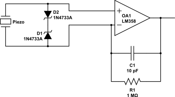
I don't really care about the actual signal waveform, but I'm anxious not to introduce delays (the key part of this is an attempt to measure the arrival time of a shockwave at various points in a piece of steel.) So, currently I'm considering adding two 5v1 zeners (because that's what I happen to have lying around) nose-to-nose across the inputs. So, the effect would be like this:
schematic

simulate this circuit – Schematic created using CircuitLab

Everything to the right of the zeners is working at present, and I'm confident that limiting the input swing to 5.8 volts will not, of itself, adversely affect the rest of the circuit's ability to do its job.

Are there any concerns that I'm missing here? Again, I do care about response time and must avoid adding lag to the system, but I don't care about distortion, or signal following accuracy, in any of the traditional "amplifier" kinds of ways.

Edit, I transcribed a subset of my actual circuit, intending to focus on the bit that I was interested in (i.e. just up to the first op-amp's input), and I fear that this was not clear. However, I also discovered, thanks for the feedback, that I had made an error in transferring my test circuit to my final. I had omitted the ground connection on the positive input to the op-amp. Oddly, it works (seven copies of it) seemingly just fine like that. Clearly, however, that needed fixing :)

\$\endgroup\$
7
  • \$\begingroup\$ How can it be working when all you have connected to the non inverting input has no dc bias? \$\endgroup\$
    – Andy aka
    Commented May 24, 2020 at 19:22
  • \$\begingroup\$ Fair question :) It leaks DC bias from the output back through that 1M resistor. It works fine in that respect. \$\endgroup\$ Commented May 24, 2020 at 22:24
  • \$\begingroup\$ The full circuit actually is the result of a discussion I had here: electronics.stackexchange.com/questions/492330/… \$\endgroup\$ Commented May 24, 2020 at 22:26
  • \$\begingroup\$ That doesn’t make it correct. As shown, your circuit is faulty. \$\endgroup\$
    – Andy aka
    Commented May 25, 2020 at 0:08
  • \$\begingroup\$ Well, if you'd like to explain why, I'm all ears. Particularly if you can explain why I have seven instances of the circuit built and all have behaved perfectly well (and yes, I'm aware that it could be luck, but that's a lot of luck). The quiescent state and dynamic behavior of the charge amp is exactly as intended, and the same, in each case. The only demonstrated problem is that I can blow it up with excessive physical stimulation to the piezo device. Or do you assert that the two are related? \$\endgroup\$ Commented May 25, 2020 at 0:23

2 Answers 2

1
\$\begingroup\$

For max dynamic range you could try to clamp the signal to the voltage rails with a germanium diode as long as your op amp can take Vcc + 0.3 V and Vee - 0.3 V. Also make sure the voltage rail can absorb the small burst of current, as long as you have small capacitors I don't think the piezo can produce that much power so it shouldn't cause too much of an issue. This solution won't cause delay.

Otherwise I think your solution in the original post is good since the signal would be theoretically be clamped at +/- (zener breakdown voltage + 0.7 V).

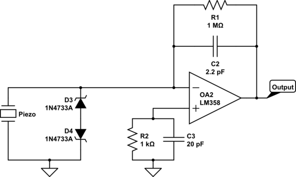
Also, I found a paper on balancing the op amp input impedance by adding a parallel resistor/capacitor to the positive input going to ground. May be worth looking into for noise reduction depending on how small your final signal will be. Here's a schematic combining both elements, component values are a guess.

Starecki, Tomasz. (2014). Analog Front-End Circuitry in Piezoelectric and Microphone Detection of Photoacoustic Signals. International Journal of Thermophysics. 35. 1-16. 10.1007/s10765-014-1715-0.

schematic

simulate this circuit – Schematic created using CircuitLab

\$\endgroup\$
2
  • \$\begingroup\$ Thank you for this. I had the problem of "don't let it swing outside the power rails" in mind when I came up with the zeners idea. I don't really want to change the op-amp that I'm using (I have a box of LM358 already :) but as James notes, it seems I only have 0.3v to play with below the rails, so even germanium (haven't used that in 40 years, but I recall that being about the forward voltage of Ge?) is a bit close for comfort. \$\endgroup\$ Commented May 25, 2020 at 13:25
  • \$\begingroup\$ Many thanks for the follow up. This looks great. I don't really need to worry about noise, or frequency response. The raw signal from the sensor readily swings more than 5v when I hit it (not the piezo, the thing that it's attached to!) with a hammer, and it will in fact be hit much harder than that (hence the concern!) Much appreciate your time and effort guiding me here. \$\endgroup\$ Commented May 26, 2020 at 15:40
1
\$\begingroup\$

What's confusing is that the + input of the LM358 (above) should be grounded to mid-supply.

A charge amplifier works by keeping the inputs to the op amp at the same mid-rail ground voltage.The output from the sensor is a current signal which charges the feedback capacitor. There shouldn't be any voltage signal directly from the piezo sensor, it should just be current. The integrator converts its input current to output voltage.

I think what's happening is that when the output from the op amp integrator hits the rails, its inputs move apart and exceed the power rail voltages which the op amp won't cope with.

The maximum input for a LM358 is 32V but the minimum limit is Vss-0.3V.

Your two zeners (5.8V limit) will still allow the input to exceed the negative rail voltage. (9V battery).

I think I would try putting a couple of ordinary 1N4148 signal diodes back to back between the op amp's inputs to limit the voltage swing of the op amp's negative input to 0.7V either side of mid-rail ground. The added diodes shouldn't affect anything until after the integrator's output hits the rails.

You could then confirm, by scoping the integrator's output that it is still hitting the rails proving that the piezo's output is indeed a current signal.

\$\endgroup\$
1
  • \$\begingroup\$ I believe that your first sentence is what Andy Aka was referring to, but I wasn't following. I would love to understand how come what I built seems to behave well in that respect. As mentioned, I've now built this seven times. Is it possible that somehow the act of measuring it (e.g. when I attach the scope probe), I'm actually correcting this error and hiding the problem? Anyway, particular thanks for actually explaining what Andy was driving at! Meanwhile, I'm going to take a close look at your solution description and try to resolve it accurately. Thanks again! \$\endgroup\$ Commented May 25, 2020 at 13:19

Your Answer

By clicking “Post Your Answer”, you agree to our terms of service and acknowledge you have read our privacy policy.

Not the answer you're looking for? Browse other questions tagged or ask your own question.