7
\$\begingroup\$

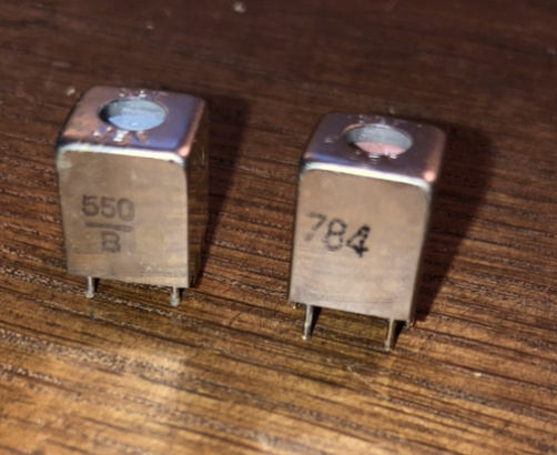
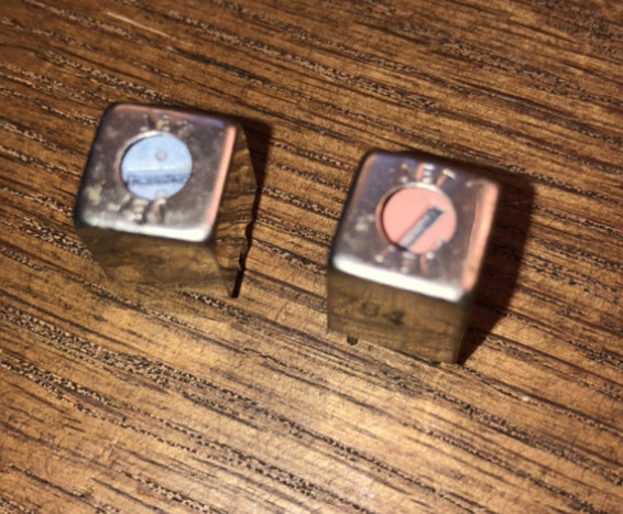
I recently came across an old radio that has these odd parts on them. They are labeled "T3" and so on, so maybe they're some kind of capacitor or transformer?

They're adjustable at the top and branded/stamped "JET" around the adjustment screw.

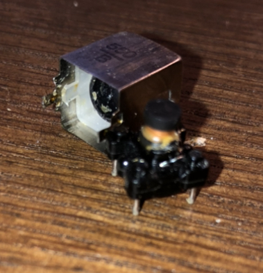
In the last picture, I carefully dissected one and it's just thin copper wire wrapped around what seems to be a ferrite/iron core.

Any ideas?

Enter image description here

Enter image description here

Enter image description here

\$\endgroup\$
2
  • 24
    \$\begingroup\$ I'm not sure I'd call that a rare component. \$\endgroup\$
    – Hearth
    Commented Apr 23, 2020 at 1:58
  • 2
    \$\begingroup\$ @VoltageSpike As the answers say, these are neither potentiometers nor variable capacitors, but actually variable inductors. The old title was way less misleading. \$\endgroup\$
    – TooTea
    Commented Apr 24, 2020 at 9:13

7 Answers 7

26
\$\begingroup\$

They're IF transformers (T is for Transformer) used in radios (relatively narrowband amplifiers at the Intermediate Frequency of usually 10.7MHz for FM and 455kHz for AM).

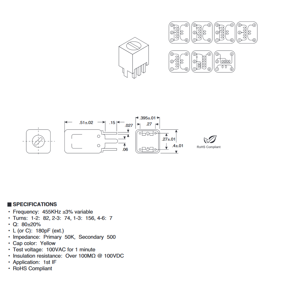
The ferrite core adjustment is for trimming the inductance to tune the center frequency, called "aligning" the radio. Below image from this datasheet.

enter image description here

There are many variations and you need some equipment to properly align a radio, which does not bode well for your chances at success.

\$\endgroup\$
3
  • \$\begingroup\$ Is there any way to identify electrical specs just by the cap color? Or is the color to code for one spec? \$\endgroup\$
    – zvolk4
    Commented Apr 23, 2020 at 20:30
  • \$\begingroup\$ Possibly. I found another datasheet with a yellow cap that is similar but not exact i.imgur.com/qcynUGU.png This kind of transformer is probably antique, I think newer designs use ceramic filters or other methods. \$\endgroup\$ Commented Apr 23, 2020 at 21:24
  • 1
    \$\begingroup\$ The red one was often part of the local oscillator, in my experience. \$\endgroup\$
    – gbarry
    Commented Apr 25, 2020 at 7:11
9
\$\begingroup\$

They are variable inductors, used for fine-tuning frequencies.

\$\endgroup\$
2
  • 1
    \$\begingroup\$ Ok, that makes total sense now. The ferrite core and wire should've been a dead giveaway haha. i hope i can buy a new one since I broke one already.. \$\endgroup\$
    – zvolk4
    Commented Apr 23, 2020 at 1:20
  • \$\begingroup\$ @zvolk4 yeah, the wire wound around something is a pretty good indication of some kind of an inductor. But, to be honest: I've did once an almost exactly opposite mistake: imagine my surprise when I've seen a high-power low-inductance wire resistor for a first time and someone told me "what? no, that's not an electro-magnet! why would we need one?". \$\endgroup\$ Commented Apr 24, 2020 at 0:16
4
\$\begingroup\$

These are variable inductors used for trimming specific frequencies. Usually, you also need an oscilloscope for repairing and re-aligning these old receivers. Here's a YouTube channel that specialises in doing exactly that: MrCarlsonsLab

Alternatively, you could measure every component in the circuit with a precise multimeter and figure out what value you're supposed to set these at by understanding what particular frequency the component arrangements are filtering out. Here are some online calculators for simple frequency filters:

https://electronicbase.net/band-stop-filter-calculator/

http://sim.okawa-denshi.jp/en/Fkeisan.htm

\$\endgroup\$
3
\$\begingroup\$

They are well known Intermediate Frequency Transformers (IFTs) and not rare. The transformer primary and secondary windings would be on a ferrite bobbin surrounded by a threaded 'cup' core. There would also be a ceramic capacitor across the primary winding. The winding ends and the capacitor leads would be soldered to the pin terminals of the IFT, enclosed in a brass or aluminium housing. By adjusting the cup core the primary winding/capacitor would be made to resonate at the required intermediate frequency. The frequency would generally be 455 kHz for AM and 10.7 MHz for FM.

\$\endgroup\$
2
\$\begingroup\$

Yes, intermediate frequency transformers used in a superheterodyne receiver. Commonly 455kHz for hf receivers. They cans be set slightly staggered to adjust the bandwidth of the if amplifier. Also 10.7 MHz transformers for FM receivers. The oscillator in the superhet receiver will also use one. The oscillator tracks the input tuner the two frequencies are feed into the mixer and four frequencies can be detected from the mixer. The signal frequency, the oscillator frequency and two heterodyne frequencies one unwanted and one wanted. A double superheterodyne receiver is preferred for the higher frequencies. Crystal filters may be used in the amplifier to give certain bandwidths. The last IF will have an output winding to match into the demodulator.

\$\endgroup\$
0
\$\begingroup\$

These are IFT coils used in radio as well as in b/w tv for converting single high to low & low to high for better response.

\$\endgroup\$
0
\$\begingroup\$

Intermediate frequency 455KHz transformer

\$\endgroup\$
1
  • \$\begingroup\$ Welcome to EE.SE. Please take care to make your answer readable. And always add some explanation. Thank you. \$\endgroup\$
    – Ariser
    Commented Apr 24, 2020 at 18:40

Not the answer you're looking for? Browse other questions tagged or ask your own question.