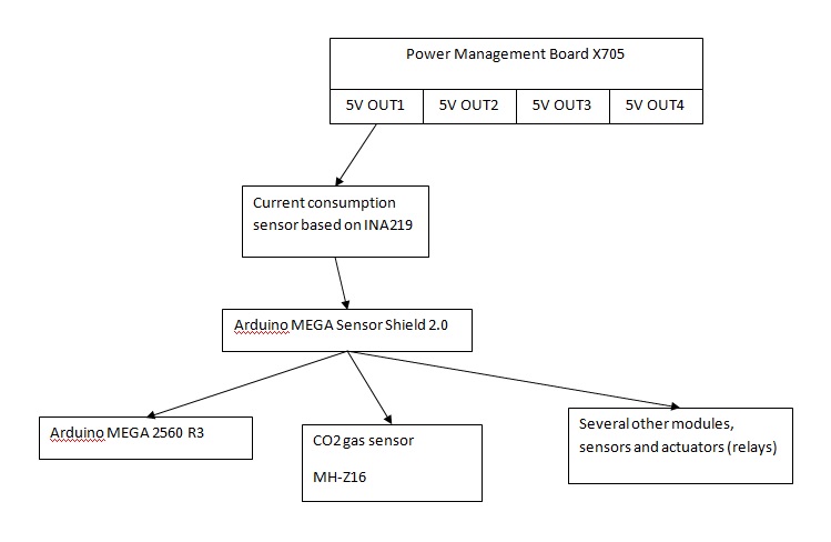
I'm building a device that contains microcontroller (Arduino) and several other modules. What makes me worry is the fluctuation of voltage at the Vcc input of one of the modules. High level scheme of power distribution is shown below:

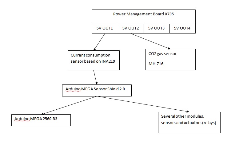
When I measure voltage with my portable voltmeter then I get stable 5.0V at OUT1, however when I measure voltage at the Vcc input of 'Arduino MEGA Sensor Shield 2.0' (which is just providing a convenient way to connect all modules to Arduino microcontroller) then I see a continuous fluctuation of voltage in the range 4.9-5.0V. So I started to power off all modules one by one and I found out that it is CO2 gas sensor that is causing this fluctuation. When CO2 sensor is powered off then Vcc is stable. Then I powered CO2 sensor directly from OUT2 of X705 like shown below:
In such setup voltage is stable and no fluctuation is observed.
While it seems that I solved the problem I still would like to understand why the problem got solved this way and here come the questions:
Question 1: From specification of X705 and all ICs it consists of I understood that despite there are 4 outputs there is still only one voltage converter (boost). So in other words this is not 4-channel power converter, but rather only 1-channel, and these 4 outputs are all connected to this single channel. If so, then why reconnecting CO2 sensor from Sensor Shield directly to X705 solves the issue with voltage fluctuation? Or I understood something incorrectly from specifications?
Question 2: X705 is rated to provide up to 8A, but all modules connected to it consume max 500mA. CO2 sensor itself consume max 85 mA. Why CO2 sensor is causing such voltage dropouts? I understand CO2 sensor has internal heater which is being switched on/off frequently, but why it has such effect on Vcc line?
X705 consists of the following ICs:
- Injoinic IP5310 Power Bank SoC with 3A charger and 3.1A discharger
- TI TPS61088 10-A Fully-Integrated Synchronous Boost Converter
- AO 4447A 30V P-Channel MOSFET
- TI NE555 Precision Timers
- TI CD4011B CMOS NAND Gates
Some links:
- X705 description can be found here
- CO2 sensor is MH-Z16
- INA219 current sensor description

