0
\$\begingroup\$

NEWOLD

I'm using Digispark Pro with my program successfully. I bought new ATtiny167 chip for custom PCB board (for HID USB device). I use the scheme from: https://electrobattery.ru/product/plata-arduino-digispark-pro-attiny167/ and this is not working. Result is: “Unknown USB Device (Device Descriptor Request Failed)”.

What I tried:

  1. I read fuse from my digispark pro (E:FE H:DD L:DF). I wrote this fuse successful. I read flash from my Digispark Pro . I wrote this flash successful. Not working.
  2. I tried this variant: How to write a bootloader and drivers for ATtiny167. same result.
  3. i Tried micronucleus 2.04 (https://github.com/micronucleus/micronucleus) with both fuse variants. same result.

Part2: I solder out chip (old chip) from my working digispark pro, which successful work with USB. And tried use this chip on my breadboard. Result: “Unknown USB Device (Device Descriptor Request Failed)”

I tried another variant: i took new chip and soldered it in digispark pro. Try 6 combination: 2 variant of fusses and 3 variant of flash (probootloaderr2.zip from http://digistump.com/wiki/digispark/tutorials/proisp; t167_default.hex dвdrom https://github.com/micronucleus/micronucleus/tree/master/firmware/releases and readed flash from my Digispark Pro). Result: “Unknown USB Device (Device Descriptor Request Failed)”

I returned old chip to digispark pro. everything works good.

WHAT the problem((( Please help

I only write fuses and flash to chip. May be i have to do anything else?

Please help.

\$\endgroup\$
9
  • 1
    \$\begingroup\$ Custom pcb? You copied the "Digispark" schematic, did you also copy the board layout and impedance matching for the USB data lines? Can you provide your layout/schematic? \$\endgroup\$
    – Ron Beyer
    Commented May 22, 2020 at 19:14
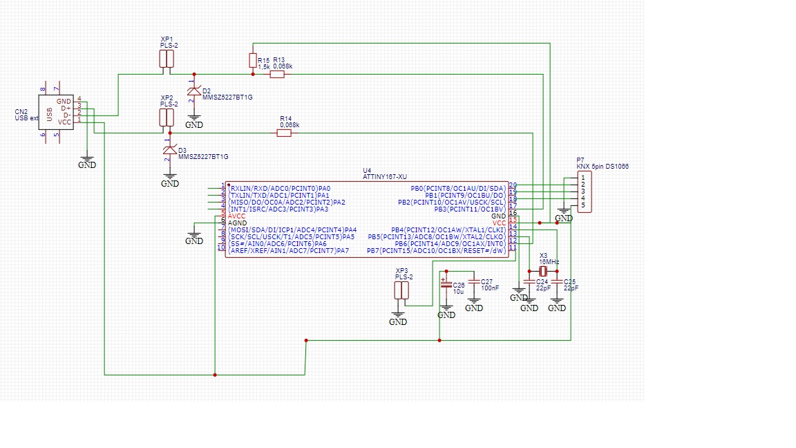
  • \$\begingroup\$ I added schematic. please see \$\endgroup\$ Commented May 23, 2020 at 5:32
  • 1
    \$\begingroup\$ Avcc and Agnd must always be connected to power and ground, even if you're not using the adc. \$\endgroup\$
    – BeB00
    Commented May 23, 2020 at 5:40
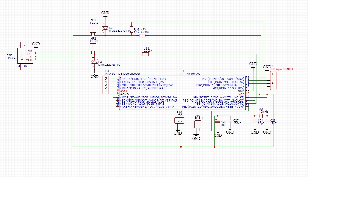
  • \$\begingroup\$ I connected pin 5 to VCC and pin6 to GND. And try again. same result( \$\endgroup\$ Commented May 23, 2020 at 7:30
  • \$\begingroup\$ If pins 5 and 6 are connected then you should show them on the schematic. GND symbols should be pointing down (towards the ground). The GND symbol represents metal plates buried in the ground. \$\endgroup\$
    – Transistor
    Commented May 23, 2020 at 8:00

1 Answer 1

1
\$\begingroup\$

I hope you did not copy the schematics. The schematics have power supply pins to the ATTiny167 not connected, so obviously it won't work.

\$\endgroup\$
6
  • \$\begingroup\$ I added my schematic. please see. power supply is connected \$\endgroup\$ Commented May 23, 2020 at 5:33
  • 1
    \$\begingroup\$ No, half of the power supply pins are disconnected. See pins 5 and 6. \$\endgroup\$
    – Justme
    Commented May 23, 2020 at 7:11
  • \$\begingroup\$ I connected pin 5 to VCC and pin6 to GND. And try again. same result( \$\endgroup\$ Commented May 23, 2020 at 7:30
  • \$\begingroup\$ I only write fuses and flash to chip. May be i have to do anything else? \$\endgroup\$ Commented May 23, 2020 at 7:55
  • 3
    \$\begingroup\$ Maybe the AVR is already broken as it was half-powered? Have you tried with an AVR that is known to be working? \$\endgroup\$
    – Justme
    Commented May 23, 2020 at 8:01

Your Answer

By clicking “Post Your Answer”, you agree to our terms of service and acknowledge you have read our privacy policy.

Not the answer you're looking for? Browse other questions tagged or ask your own question.