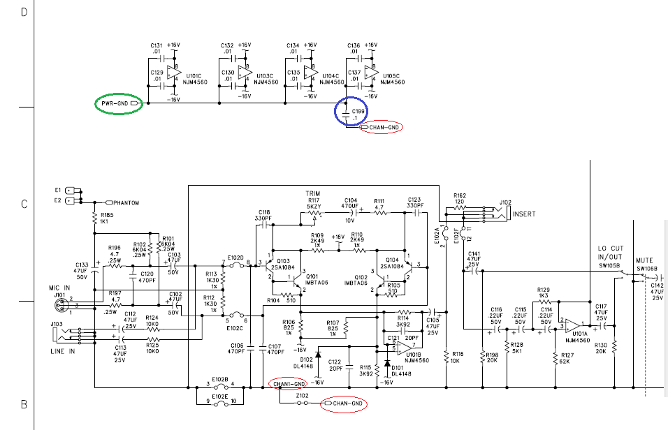
I've read some questions and answers here about making 2 separate grounds - one for signal, second one for power. Every question was about the case where the grounds meet each other in one point.
I came across mixer schematic and there are 2 grounds: channel ground (signal ground) and power ground. They aren't joined together, the thing that joins them is a capacitor. First question is: can it work like that? The answer is probably yes, because it's a schematic of a working device that is on the market. Second question is - would it be better to join the grounds by resistor not by a capacitor? I've read and article about HBR (hum breaking resistors) and maybe this would be a proper application of such element?
And final question is - how to run 2 grounds on the PCB? Should power ground or signal ground be distributed as a plane? Or no ground planes?
Extra question is - to which ground should i connect the shield of the shielded cable?

