8
\$\begingroup\$

Is it possible to design a voltage divider circuit with switches that uses zero current, or very low current? Would it work to use a transistor to connect/disconnect the end of resistor string from ground?

Background

The circuit will do two things. Each switch in the circuit will wake up a IC (ATMEGA328P) by using a transistor to send an interrupt pin LOW. Once the IC wakes up, the ADC will sample the voltages coming from the circuit, allowing the IC to know which button was pressed.

The entire project will be battery operated, and having this voltage divider may significantly impact battery life.

The project will 1) read files from an SD card, 2) go to sleep, 3) wake and play sounds when one of 16 buttons is pressed, and 4) go to sleep and repeat process starting at #3 on button press. I anticipate that when it is running it have a significant current draw.

Existing Voltage Divider Circuit

enter image description here

Possible Transistor Solution

Placing a transistor between the end of the resistor string and ground, and having the button press activate the transistor, connects the end of the voltage string to ground. This will result in an initial voltage reading of 5V, and once the transistor is on, the actual read voltage will be the intended voltage. I have no idea if this will work.

possible voltage divider circuit with transistor

Other Solutions

Per question 28897 I could use high values of resistors such as 10 MOhm. But this will still have a current draw of hundreds of nA. I'd prefer zero.

\$\endgroup\$
10
  • 3
    \$\begingroup\$ If you use a 1000mAh battery with 5V across 10 MOhm, the battery will last 228 years, or 6 years with a tiny 30 mAh button lithium cell. Every sample you take with an ADC will charge or discharge a cap, as well. Also, ADC input impedances on controllers tend to be in the 10K range, and you'll be charging a cap through that with every sample. Given that, are you sure that your nA solution would really be a noticable impact on battery life? \$\endgroup\$ Commented Nov 29, 2012 at 17:08
  • \$\begingroup\$ You're right, given that the sum of the quiescent current of the voltage regulator and the MCU itself (when asleep) is likely at least 10 uA. I'm just trying to cut down any unnecessary current drain. \$\endgroup\$ Commented Nov 29, 2012 at 17:21
  • \$\begingroup\$ @n.taco Some additional data would help. What's your max battery voltage? What's your Vcc voltage? How is the uC powered (through a linear regulator, or switch mode, or directly from the battery)? \$\endgroup\$ Commented Nov 29, 2012 at 18:43
  • \$\begingroup\$ The battery source will likely be 4 D cells. The voltage regulator is a Maxim MAX667 (linear voltage regulator) which will supply power to all devices (no devices will see the battery voltage, except the regulator). Vcc is 5V. \$\endgroup\$ Commented Nov 29, 2012 at 19:10
  • \$\begingroup\$ @n.taco BTW, write component designators in your schematics. It's much easier to say "Q23" than "3rd bottom BJT from the right". Read this. Your risk of hypertension is greately increased, if you don't follow these guidelines on EE.SE. Fair warning. \$\endgroup\$ Commented Nov 29, 2012 at 20:10

4 Answers 4

5
\$\begingroup\$

New answer

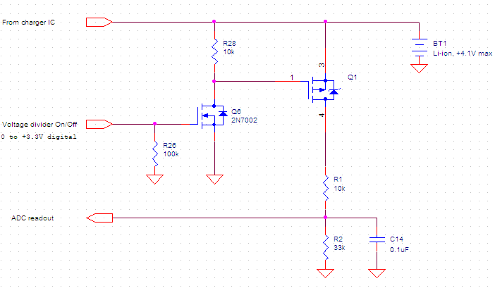
Your approach can work. But, your 2nd schematic has a bug, I think. The ADC will always see Vbe of the transistor, which is always 0.7V or so.

This variation shouldn't have this problem, because there's a resistor R39 between base and ADC.

enter image description here

Old answer, which wasn't an answer

The divider can be switched with a transistor to save the battery. However, it has to be a high side switch. If you switch at the ground, then the battery voltage will appear on the A/D pin, which could damage the input.

(Originally, the schematic was posted in this thread.)

\$\endgroup\$
4
  • \$\begingroup\$ How would this idea work with the constraint that the switches turn the transistor on? \$\endgroup\$ Commented Nov 29, 2012 at 17:16
  • 1
    \$\begingroup\$ Replace the digital signal divider On/Off, which controls the transistor, with a manual switch. How about that? \$\endgroup\$ Commented Nov 29, 2012 at 17:23
  • \$\begingroup\$ 1. I'm having a hard time seeing how I would extend this to identifying which switch is pressed. For N switches, wouldn't I have to have N transistors plus the resistors for dividing the voltage? 2. If Vcc <= ADC max voltage, would I be able to switch ground? In that case the voltage at the ADC will start at 5V but decrease to the divided voltage, correct? \$\endgroup\$ Commented Nov 29, 2012 at 19:42
  • \$\begingroup\$ @NickAlexeev I see the bug, thanks for pointing that out; I also didn't realize that this could be done with one transistor. This looks great, I'll be trying it out this weekend. \$\endgroup\$ Commented Nov 30, 2012 at 15:35
3
\$\begingroup\$

You don't even need a transistor to disconnect the resistor string, you can just connect it to an MCU output pin. Set it to the same value as the other end of the string, and it will use near-zero current. I have used this approach and it works fine.

(In your diagram, give the transistor its own ground and connect the MCU pin to the bottom of the resistor string).

\$\endgroup\$
3
  • \$\begingroup\$ Are you referring to the second diagram or the first one? \$\endgroup\$ Commented Nov 29, 2012 at 17:18
  • \$\begingroup\$ Also, if both pins are HIGH, will there be any voltage drop in the divider? \$\endgroup\$ Commented Nov 29, 2012 at 17:19
  • \$\begingroup\$ First diagram (have edited your post to include them directly). If both ends are high, then the voltage at all points along the divider will be high and no current will flow. \$\endgroup\$
    – pjc50
    Commented Nov 29, 2012 at 18:16
2
\$\begingroup\$

Is it possible to design a voltage divider circuit with switches that uses zero current...

This should do the trick and no ground switching required. A divider is connected to the battery only when a switch is closed and the ADC input is pulled to ground when all switches are open.

For 5V Vcc, the ADC input is:

  • 5.0V = SW1 closed
  • 3.3V = SW2 closed
  • 1.7V = SW3 closed
  • 0V = all switches open

Of course, you can adjust the resistor values to your liking.

enter image description here

\$\endgroup\$
4
  • \$\begingroup\$ That approach can be good if one is using quality switches. It can be very bad if one is using carbon domes on a PC board, since the resistance of a lightly-pressed button may be less than 1K, or more than 100K, or anywhere in-between, and such resistance may appear to stay reasonably stable for a significant fraction of a second. While it's generally fine for the system to ignore light button pushes, it's generally annoying to have a light push on one button be interpreted as a totally different button. \$\endgroup\$
    – supercat
    Commented Nov 30, 2012 at 18:24
  • \$\begingroup\$ I agree; using a pressure sensitive resistor instead of a reasonable approximation of geniune, open when off, short when on, switch will, in this circuit, lead to unpredictable results. \$\endgroup\$ Commented Nov 30, 2012 at 20:05
  • \$\begingroup\$ In many applications, a carbon-dome contact, even though it behaves as a pressure-sensitive resistor, may be used as a switch (though adding some hardware or semi-hardware hysteresis, can certainly help). I just wanted to make sure readers knew that this is not one of those applications. \$\endgroup\$
    – supercat
    Commented Nov 30, 2012 at 20:56
  • \$\begingroup\$ Indeed and, sadly, it's a distinction that has to be made. Just because something is called a "switch" doesn't necessarily mean it's a good approximation of an ideal switch. \$\endgroup\$ Commented Nov 30, 2012 at 21:04
1
\$\begingroup\$

Given two I/O pins with reasonably-consistent switching thresholds, one could wire a grounded cap to each processor pin via small resistor, tie one cap to each end of the resistor string, and have each switch connect a tap on the string to VDD or ground (whichever is more convenient; I'll assume VDD for this discussion). Have significant resistance between either end and the first switch. Sometime when no switch is pushed, ground both pins long enough to discharge the caps; then float one and set the other to VDD. Time how long it takes for the floating pin to change state. If the inputs' thresholds might differ, repeat the test for the other input. Then ground both pins, and then float them--this is the idle state.

Once a pin has been observed to change state, ground both pins long enough to discharge the cap, and float them. Time how long it takes for each pin to change state. The ratio of this time to the baseline measured above will tell you the resistance from each pin to VDD. Ensure that the sum of the two measurements is reasonably close to the total resistance of the string (otherwise the button isn't making good contact, so the reading may be faulty).

If the processor may draw excess current when inputs are floating away from the rails, it may be a good idea to periodically discharge the caps even when no button is pushed. If this is done, quiescent currents for the system should be pretty minimal.

\$\endgroup\$
2
  • \$\begingroup\$ Interesting idea. Won't the capacitors be drawing current continuously? \$\endgroup\$ Commented Dec 3, 2012 at 19:51
  • 1
    \$\begingroup\$ @n.taco: Increasing the voltage on a cap by a certain amount requires adding an amount of charge (in coulombs) equal to the change in voltage (in volts) times the capacitance (in farads). Decreasing the voltage requires removing charge. One ampere represents one coulomb per second. Charging a capacitor and dumping its charge to ground at some periodic rate will require an amount of current equal to the charge per cycle times the frequency. If the capacitor spends most of its time sitting at a constant voltage, however, it will use essentially zero current during such time. \$\endgroup\$
    – supercat
    Commented Dec 3, 2012 at 20:01

Your Answer

By clicking “Post Your Answer”, you agree to our terms of service and acknowledge you have read our privacy policy.

Not the answer you're looking for? Browse other questions tagged or ask your own question.