3
\$\begingroup\$

First and foremost I have a question regarding the MMF distribution in a Motor produced by a single coil. I found a picture here: enter image description here Why does the MMF not start at 0 at 0°? When I apply the $$NI=\int{H \mathrm{d}l}$$ with a curve with a small angle opening around the 0 point (horizontal arrow), I'd get 0.

And my second question is the following: What's the easiest explanation why the fundamental of the permanent magnet flux should be perpendicular to the fundamental MMF to produce the maximum possible torque from a PMSM (without saliency)? Edit: I'd really prefer a mathematical derivation of the torque equation to understand the behaviour.

\$\endgroup\$
1
  • \$\begingroup\$ The MMF does not start at 0 at 0 degrees because 0 degrees has been arbitrarily selected as the center of the A-A' coil. The MMF changes (positive/negative) at the coil slots. \$\endgroup\$ Commented Jun 3, 2020 at 21:21

1 Answer 1

1
+50
\$\begingroup\$

Regarding your first query you cannot just choose any curve you like to calculate mmf. The mmf here is due the conductor so you have to include it in the curve while applying ampere's circuital law to calculate mmf due to that conductor. And the 0 is all about chosen reference. Here the maximum of fundamental mmf waveform is chosen as 0 arbitrarily.

If you don't get it like this see the diagram (attached) at chosen zero. Consider the mmf due to single conductors,you will see that both the flux add up as they are in same direction in the the region around zero. enter image description here
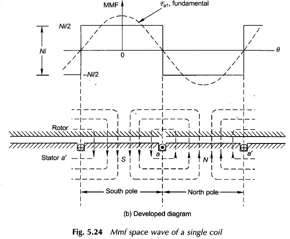
And as for the sinusoidal peak (assumed that you know about fourier series). The given waveform as we see is a even periodic waveform so the components are likely to contain cosine fundamental and harmonics.

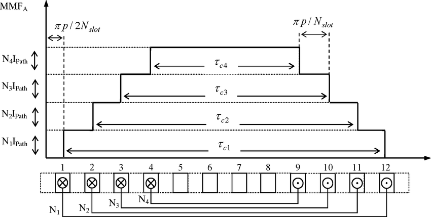
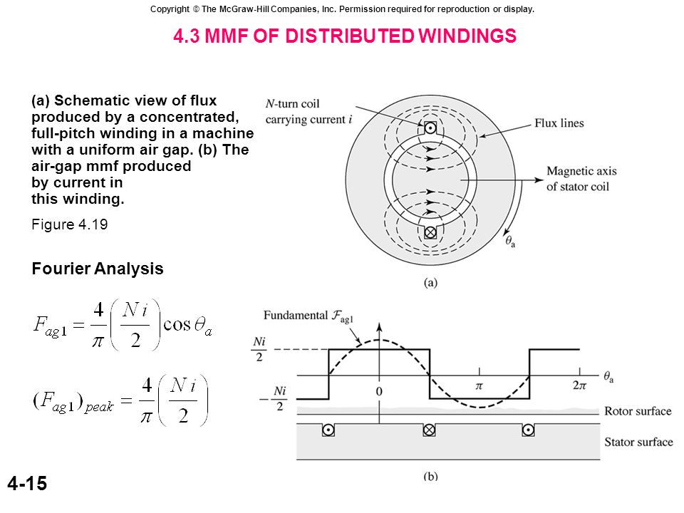
In case you assume a distributed conductor (attached) you can easily see why there is a peak at the position shown. Don't get confused by the details of waveform just see them and get a fair idea of what is happening here. As you can see in these images the reference is chosen at 0 mmf and not at maximum as before. It is chosen arbitrarily. What really matters is the shape of waveform and its relative position w.r.t to rotor mmf waveform. enter image description here enter image description here
For maximum torque.... see it like this, the torque acts in order to align the two mmf either parallel or antiparallel and we see the maximum misalignment is when the two mmf are perpendicular to each other.

Mathematically this is represented by the equation

$$Te = -(π/8)P2ØFs\sinδs$$ Nm

P = Number of poles

Ø = Resultant air gap flux per pole

Fr = Rotor mmf

Fs = Stator mmf

The torque is proportional to product of magnitude of two mmfs and sine of angle between them. The part is maximum at angle = 90.

Images used:

https://www.eeeguide.com/wp-content/uploads/2015/12/MMF-of-Distributed-AC-Windings1.jpg

https://www.researchgate.net/profile/Behrooz_Mirafzal/publication/3270589/figure/fig10/AS:394675438538755@1471109365128/MMF-profile-of-phase-A-of-the-stator-winding-over-180-electrical-degrees-over-a-pole.png

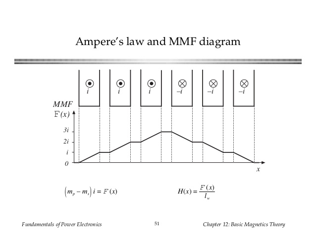
https://image.slidesharecdn.com/chapter12-170102174253/95/chapter-12-50-638.jpg?cb=1483379253

I have tried to keep the answer as simple and as informative as possible. The answer is open to advice and content addition.
\$\endgroup\$
4
  • \$\begingroup\$ Thanks for the contribution. 'Pure' Ampere's law doesn't say a word that you 'have to' include conductors. But okay, I buy it that the reference is arbitrarily chosen. I also know this equation for torque calculation but I've never sawn a derivation of this equation which fitted to the presented diagrams. I should have stated that I'm more specifically looking also for a derivation of this equation. \$\endgroup\$
    – Steradiant
    Commented Jun 3, 2020 at 7:07
  • \$\begingroup\$ Ampere's law says ∮B⋅dl=μ.Ienc=0 around the closed loop. It doesn't say B=0 for all points on the loop. Note that the value of an integral does not uniquely determine the integrand. And your doubt is based on such an assumption. \$\endgroup\$ Commented Jun 3, 2020 at 8:19
  • \$\begingroup\$ Yes but if I e.g. apply Ampere's law to my picture for a few degree around the 0 point (horizontal axis) I'd get \$2Hg=0\$ if I assume equal airgap length \$g\$ and infinitely high permeability of the iron core. If I'd apply it to a closed loop which also encloses a conductor I'd get \$2Hg=I\$ \$\endgroup\$
    – Steradiant
    Commented Jun 3, 2020 at 8:28
  • \$\begingroup\$ hope this courses.lumenlearning.com/physics/chapter/… satisfies your curiosity about sine of the angle in torque equation. The more complex torque equation like synchronous machine torque are trickier to derive by bottom up approach using lorentz force. They can be derived easily by calculating the rate of change of store magnetic energy is the air gap of machine. This paper here people.ucalgary.ca/~aknigh/electrical_machines/fundamentals/… this beautifully. \$\endgroup\$ Commented Jun 4, 2020 at 5:02

Your Answer

By clicking “Post Your Answer”, you agree to our terms of service and acknowledge you have read our privacy policy.

Not the answer you're looking for? Browse other questions tagged or ask your own question.