2
\$\begingroup\$

Overview:

I am currently working on a project that requires a 24v alternator, which is powered by a mower engine.

This engine in particular runs around 3,000 RPM, and does not exceed 3,200 RPM (based on a few quick tests with a cheap tach).

The main reason for this question is that I am trying to understand the power output relationship between the alternator and engine.

Example:

I did a bit of research and see that alternators, which conform to ISO 8854, are rated as IL/IRA VTV. Where IL is the idle amperage output, IR is the rated amperage output, and VT is the test voltage.

However, when looking at alternators online, these metrics are often left out, which leads me to believe I may be incorrectly interpreting their meaning.

For example, and as reference to the questions below, take this Delco 10SI (1102916), which is rated for 40A @ 6,000 RPM.

Questions:

If you know the engine runs at 3,000 RPM, with a max of 3,200 RPM; Do you gear your alternator pulley in such a way that maps the running engine RPM (3,000) to the alternators rated RPM (6,000) to provide the 40A regularly? Or, will pushing 40A continuously burn the alternator out? In other words, if the measurements provided for the alternator are based on 6K RPM, is that peak (highest RPM the alternator should see)? or average (average running RPM)?

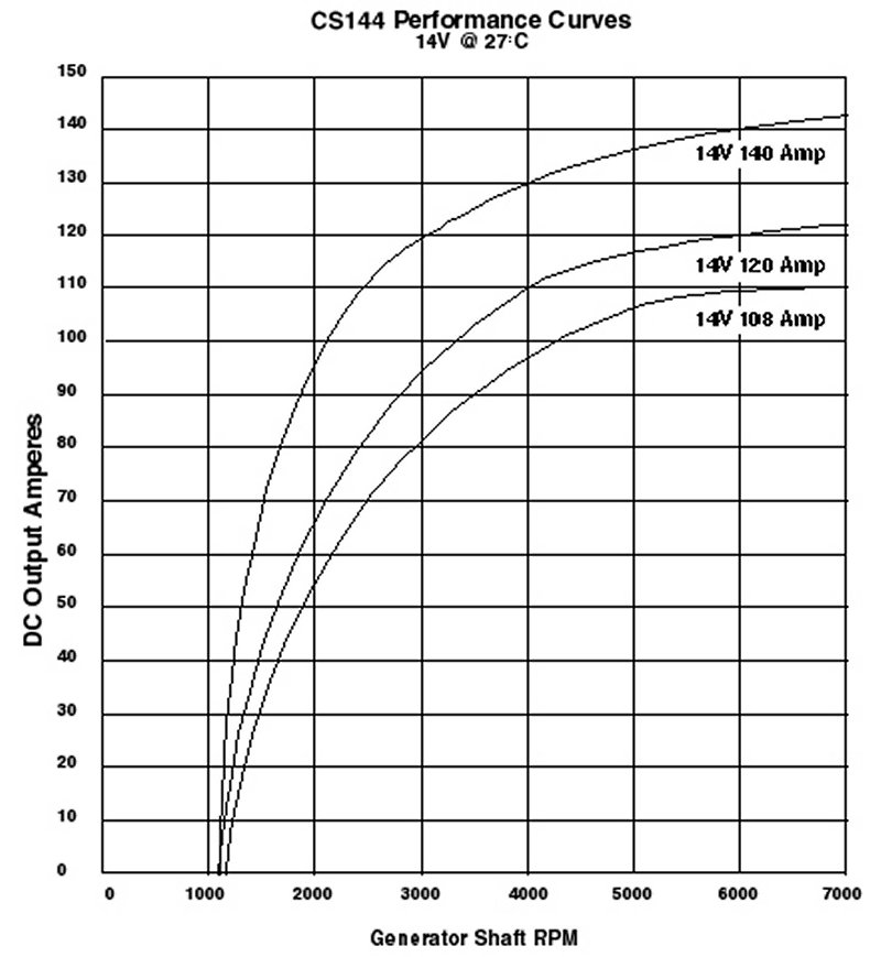
If it is peak RPM, can you just linearly extrapolate and say @ 3,000 RPM the alternator will provide half the current (20A)?

Background:

From an application standpoint, the 24v alternator will be used to charge 2 12v 55Ah (wired in series @ 24v). The expected engine run-time is around 1 hour. The goal being to charge the batteries, as the mower engine is running, for that hour duration.

\$\endgroup\$
2
  • \$\begingroup\$ Cross posted here: mechanics.stackexchange.com/q/77230/10976 \$\endgroup\$
    – Solar Mike
    Commented Jun 9, 2020 at 18:17
  • \$\begingroup\$ A normal three phase synchronous generator with field winding regulation isn’t that sensitive on speed. I don’t have exact figures but you can get close to full rated current over a fairly broad RPM range. \$\endgroup\$
    – winny
    Commented Jun 9, 2020 at 18:18

2 Answers 2

1
\$\begingroup\$

The purpose of a vehicle alternator is to feed various electrical loads as well as to charge the vehicle battery.

The highest current would be drawn from the battery during cranking, with the alternator making up for that after starting the engine. Likewise, after discharge with the engine stationary.

Since the battery would get discharged and charged in quick succession, its depletion would be quite low. The charging current would also not be very high during constant-voltage charging by the alternator (no current control).

For the current project, the extent of discharge of the batteries would be a key factor in estimating the maximum charging current that would be required.

Charging current = (Alternator voltage - Battery voltage) / Battery internal resistance

It is assumed that the batteries would be sufficiently depleted after feeding external loads.

It would be necessary to ascertain that the magnitude of the charging current would not be detrimental to the battery. Otherwise, the engine would require to be throttled in order to generate a lower current.

The following additional information may be of use.

An automobile engine generates maximum torque at around 2000 RPM. Best fuel efficiency would be obtained at around that RPM making it the optimum coasting RPM.

Automobile alternators are designed for higher frequencies to achieve size reduction and for ease of filtering out output ripple (with the battery itself functioning as a capacitor at the higher frequencies).

It has been determined that, above 600Hz, the conversion efficiency of the alternator would drop on account of skin effect and result in flattening of the speed/power curve.

A 12 pole alternator would generate 600 Hz at 6000 RPM. Therein lies the significance of the 6000 RPM rating.

A 3:1 pulley ratio would ensure an alternator RPM of 6000 at an engine-coasting RPM of 2000.

The IL/IRA VTV rating specifies the maximum output current IL at idling RPM, the maximum output current IR at 6000 RPM at a test voltage of 13.5 V.

The actual alternator output current would be dependant on the load. With the engine idling at 1000 RPM and driving the alternator at 3000 RPM, it would be capable of sourcing 50-80 % of the rated current.

The alternator RPM could exceed 10,000 but should not exceed 18000.

The flattening of the speed/power curve inherently protects the alternator from overcurrent damage at higher speeds.

\$\endgroup\$
5
  • \$\begingroup\$ Thank you @vu2nan, I would up vote but currently don't have enough rep. Just to close the loop, I wanted to ask a couple related questions: 1.) Providing that my engine runs @ 3K RPM, it would make sense to run a 2:1 ratio, so the alternator would spin @ 6K. But, would this burn the alternator if running at this RPM for an hour? 2.) In terms of measuring the discharge rate; If you know your average system load is 20A (motor controller, micro, motors, transceiver), pulling from 50Ah AGM batteries in series, for an hour, how would you go about calculating the theoretical discharge rate? \$\endgroup\$
    – Birts
    Commented Jun 11, 2020 at 17:31
  • \$\begingroup\$ Anytime, Robby, and no bother about the upvote. Running the alternator at 6000 RPM for an hour would not burn it. Your battery charge would get depleted by around 40% with a 20A draw for an hour. (55Ah batteries in series will deliver 55Ah only!). The question is whether the maximum charge current delivered by the alternator to a 40% depleted battery would be detrimental to the battery. \$\endgroup\$
    – vu2nan
    Commented Jun 12, 2020 at 5:29
  • \$\begingroup\$ That makes sense @vu2nan. I was able to pull the datasheet for the batteries being used, which I have attached to the original post. Based on that, it indicates an internal resistance of ~9.0mΩ. This should help me calculate the charge current in the formula you mentioned above. In their example, it was around 2.45V/cell. Finally, the last question is, now that I have linked the charge characteristics, this *should help me understand the sweet spot for charging capacity, right? In other words, tune the alternator RPM, such that it delivers a safe amount of current to recharge the system? \$\endgroup\$
    – Birts
    Commented Jun 12, 2020 at 8:08
  • \$\begingroup\$ Hi Robby, The internal resistance would increase with decreasing state-of-charge. I suppose you would need to carry out some trials to decide on the parameters. Have fun! \$\endgroup\$
    – vu2nan
    Commented Jun 12, 2020 at 14:57
  • \$\begingroup\$ Thank you, Robby. \$\endgroup\$
    – vu2nan
    Commented Jun 22, 2020 at 10:28
1
\$\begingroup\$

Doesn't look very linear to me (CS144 alternator performance from this website:

enter image description here

\$\endgroup\$

Your Answer

By clicking “Post Your Answer”, you agree to our terms of service and acknowledge you have read our privacy policy.

Not the answer you're looking for? Browse other questions tagged or ask your own question.