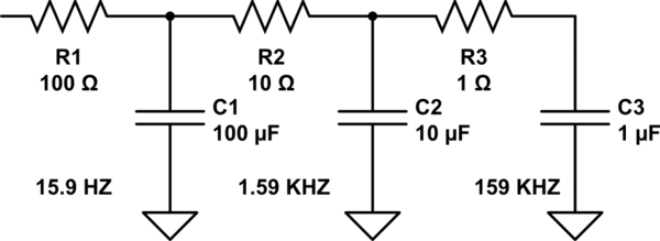
I would say the second and third stages are there to deal with self-resonance issues in the capacitors. (So this really isn't a "third-order filter", for any practical purposes.)
If the capacitors were ideal capacitors, then the second and third stages would have no appreciable effect. In an ideal capacitor, the impedance of the capacitor keeps getting lower as the frequency gets higher.
In the real world, all capacitors have some parasitic inductance. At low frequencies, this effect of this parasitic inductance is inconsequential, so the impedance-vs-frequency relationship resembles an ideal capacitor. But at higher frequencies the effect of the parasitic inductance becomes more and more significant (the capacitor actually looks like an inductor-capacitor "LC" circuit). At some point there will be a resonant frequency just like with any other LC circuit, and beyond that frequency the impedance of the capacitor will increase as frequency increases, just like an inductor. At this point the low-pass filter is no longer a low-pass filter!
https://resources.pcb.cadence.com/blog/2019-capacitor-self-resonant-frequency-and-signal-integrity
As you'd probably imagine, larger capacitors have a lower self-resonant frequency and smaller capacitors have a higher self-resonant frequency. So, it is a common practice to put multiple capacitors in parallel -- for example a 0.1µF capacitor in parallel with a 10µF capacitor -- to overcome this effect. Once the frequency gets high enough that the 10µF capacitor is no longer effective, the 0.1µF capacitor is still acting as an effective capacitor so the circuit overall still works.
The extra resistors in this circuit are new to me, but as this article suggests perhaps they are there to dampen out other resonant effects that could happen otherwise.
https://incompliancemag.com/article/using-capacitors-in-parallel-dangerous/

