1
\$\begingroup\$

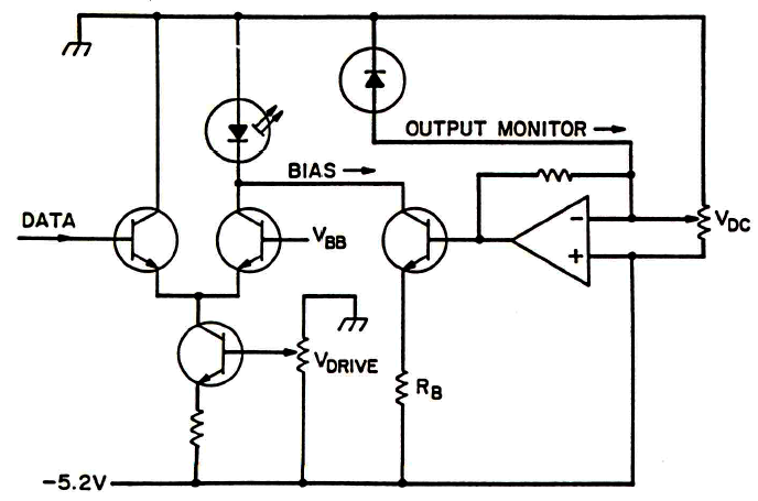
I have some problems on understanding how this circuit works. Its aim is that of:

  • bias correctly the LASER diode at left
  • send a signal (DATA) to the LASER diode
  • stabilize the working point of the LASER diode through the feedback system at right

enter image description here

My doubt is about the feedback system at right. I'd say that it will be useful if:

  • when the light power is too high, the photodetector makes the bias current of the LASER reduce;
  • when the light power is too low, the photodetector makes the bias current of the LASER increase;

But this schematic confuses me (also because GND and VCC have are taken in a different way). Suppose the light emitted power is too high: the photodetector (a photodiode, I suppose) is flown by a higher current from GND to -5.2V. What does this current cause to the operational amplifier? It is an inverting op amp but I do not know how it works in this case, since I do not know if the current provided by the photodetector goes towards the amplifier output through the feedback, or if it goes towards the resistor where it is written VDC.

\$\endgroup\$
3
  • 3
    \$\begingroup\$ The feedback system is in the right part of the schematic, not the left. \$\endgroup\$
    – The Photon
    Commented Jul 6, 2020 at 18:17
  • \$\begingroup\$ @ThePhoton thank you! Now I have corrected it \$\endgroup\$
    – Kinka-Byo
    Commented Jul 6, 2020 at 18:22
  • 1
    \$\begingroup\$ This circuit can't work : the current coming from the photodiode and from Vdc are positive (I mean entering the - input of the AOP). Hence the output of the AOP try to be more negative than -5.2V. \$\endgroup\$
    – andre314
    Commented Jul 6, 2020 at 19:11

2 Answers 2

1
\$\begingroup\$

The pot labeled Vdc and the photodiode both supply variable amounts of current to the negative node of the op amp. As such, the output must respond by going lower in order to compensate. As long as the op amp is within its operating range, the output will do what is needed to keep the negative input at the same voltage as the positive input: -5.2V.

When the op amp output goes lower, the LED current is decreased due to the reduced voltage drop across Rb.

\$\endgroup\$
2
  • \$\begingroup\$ Why will the laser current decrease? If the output voltage of the op amp lowers, I'd say that the transistor driven by it will provide less current, and so less current is subtracted to the laser diode \$\endgroup\$
    – Kinka-Byo
    Commented Jul 6, 2020 at 18:41
  • 2
    \$\begingroup\$ @Kinka-Byo, the current from the BJT attached to the op-amp isn't subtracted from the laser current, it's added. \$\endgroup\$
    – The Photon
    Commented Jul 6, 2020 at 19:04
0
\$\begingroup\$

This circuit can't work :

If you take the sign-convention that currents entering the - input of the AOP are "positive", then the currents coming from the photodiode and from Vdc are both positive,

This implies that the output of the AOP try to be more negative than -5.2V.

If the negative power supply of the AOP is -5.2V then the transistor (the one at its output) is blocked.

If the negative power supply of the AOP is -15.V then the transistor is dead (inverse Vbe max not respected).

\$\endgroup\$
6
  • \$\begingroup\$ What is an "AOP" and how is it related to this circuit? \$\endgroup\$
    – The Photon
    Commented Oct 21, 2020 at 4:33
  • \$\begingroup\$ an "AOP" is an Operational Amplifier. It is the triangle in the schematic \$\endgroup\$
    – andre314
    Commented Oct 21, 2020 at 4:35
  • \$\begingroup\$ I don't know where OP got this diagram, but it's possible the amplifier is not exactly what we'd normally call an op-amp. For example there could be a deliberate 1 or 2 V offset between the inputs. \$\endgroup\$
    – The Photon
    Commented Oct 21, 2020 at 4:38
  • \$\begingroup\$ I'm not aware of such amplifier. I'd rather say it's more likely an error in the schematic. \$\endgroup\$
    – andre314
    Commented Oct 21, 2020 at 4:41
  • \$\begingroup\$ Maybe the + input of the amplifier should be connected to the cursor of the potentiometer (instead of negative power supply) ? (not a good design) \$\endgroup\$
    – andre314
    Commented Oct 21, 2020 at 4:48

Your Answer

By clicking “Post Your Answer”, you agree to our terms of service and acknowledge you have read our privacy policy.

Not the answer you're looking for? Browse other questions tagged or ask your own question.