0
\$\begingroup\$

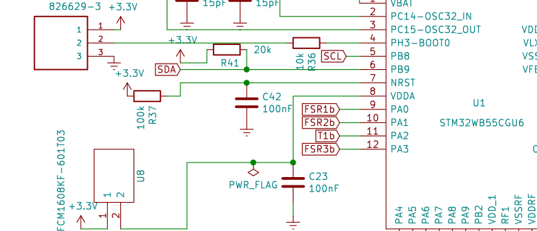
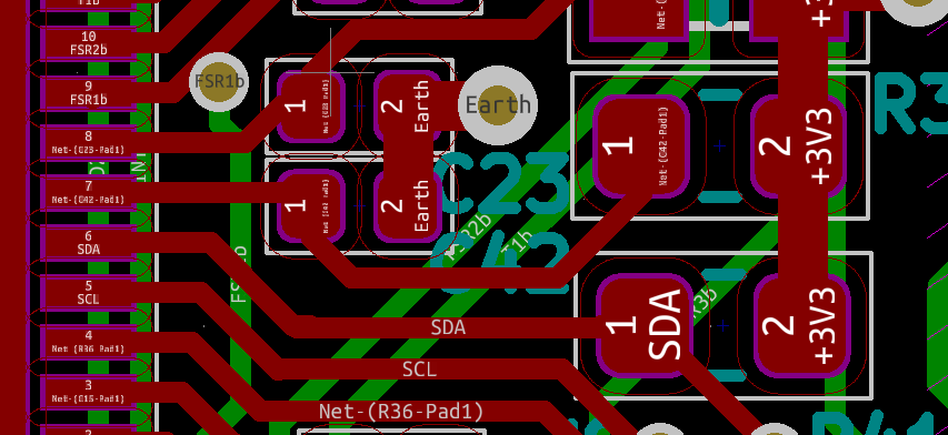
I have a custom board STM32WB55CGU6 with a reset pin connected to a pull-up resistor and a capacitor as shown in the schematic and PCB layout below (connected to the reset pin 7):

enter image description here enter image description here

Using an oscilloscope, I obtained the following signal below between the resistor and capacitor of the reset as well as VCC: enter image description here
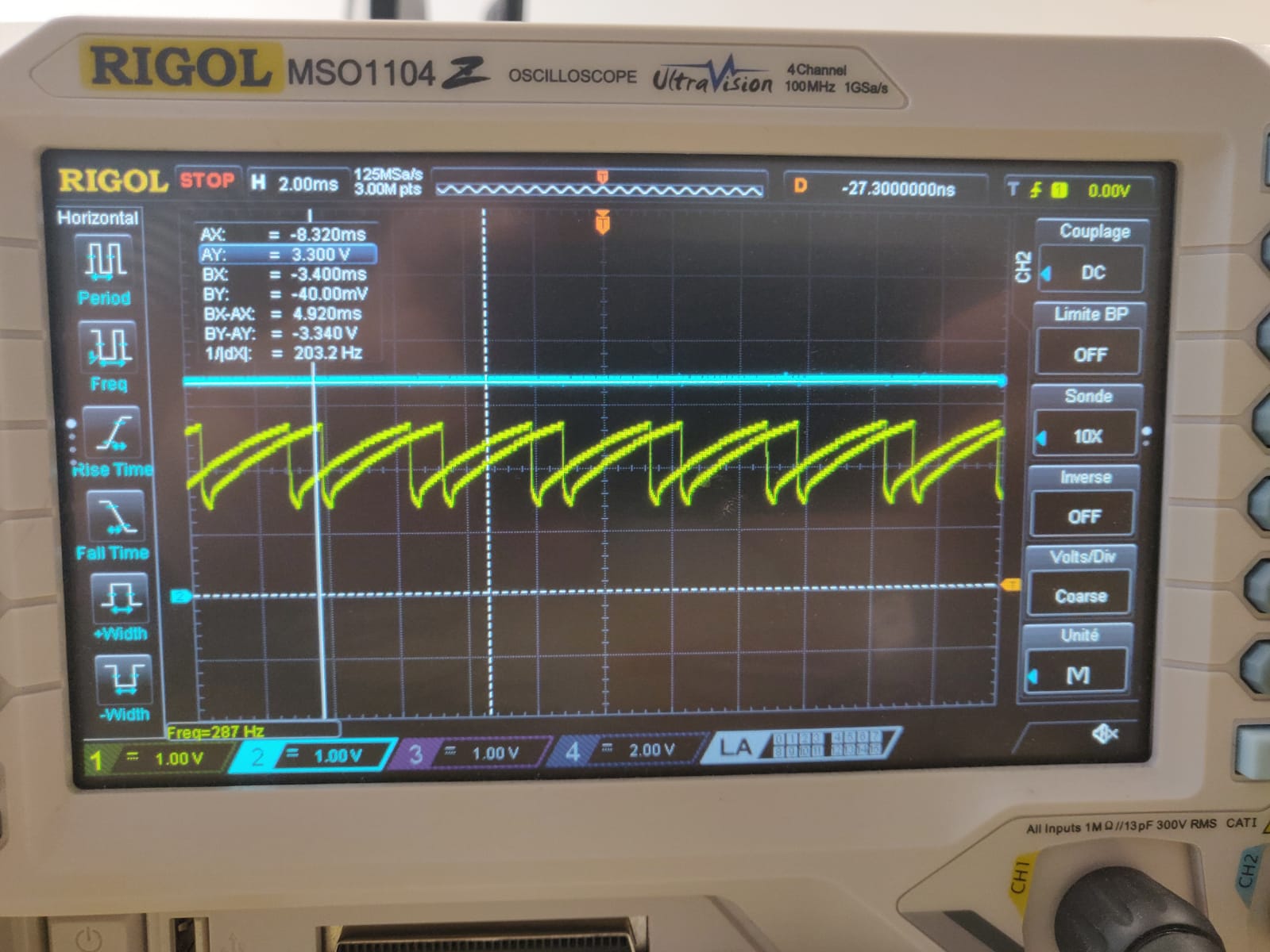
Normally, from what I understand I am supposed to obtain a value of 3.3V at this point. I think that there is a problem with the capacitor but using a multimeter, I am able to obtain a value close to the actual value of the capacitor. Any other ideas on why I would have this?

UPDATE: After removing the pull up resistor as recommended, the signal remains the same.

Also, here is the full schematics. Please note that for the moment I have modified it slightly, changing the pins of PA13, PA14 to SWDIO and SWCLK respectively to test the PCB using a ST-Link V2.enter image description here
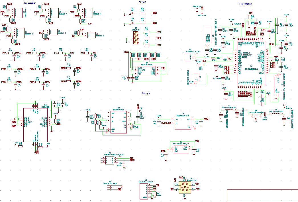
In addition to this, I have weird signals in my SWCLK and SWDIO pins.

\$\endgroup\$
17
  • 1
    \$\begingroup\$ I've no time to write a proper answer but... Your 100K resistor may be too high considering the input current of the pin is maybe 0.6..2 uA. With the slow rise time of your RC circuit, the change in input current may cause the oscillations you see. In short, replace the 100K with (say) 10K or put 10K in parallel with the 100K then try again and edit your findings into your question. \$\endgroup\$
    – TonyM
    Commented Jul 8, 2020 at 10:21
  • 1
    \$\begingroup\$ The STM32 does not need an external resistance. It is not even recommended to put an external resistance there under normal circumstances. \$\endgroup\$
    – Justme
    Commented Jul 8, 2020 at 11:31
  • \$\begingroup\$ Please measure Vcc with your other oscilloscope channel. \$\endgroup\$
    – winny
    Commented Jul 8, 2020 at 11:51
  • 1
    \$\begingroup\$ I'd suspect wrong value on the decoupling cap. If you use the wrong one on /reset, the MCU will go bananas. Maybe it's accidentally 100uF or something like that? \$\endgroup\$
    – Lundin
    Commented Jul 8, 2020 at 13:51
  • 2
    \$\begingroup\$ The new full schematics are downsampled to be almost illegible. Put more higher res picture please. Your edit suggests you see this ramp on VCC too, so it must be your power supply acting up. \$\endgroup\$
    – Justme
    Commented Jul 8, 2020 at 15:25

1 Answer 1

3
\$\begingroup\$

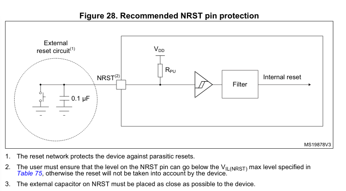
The STM32 has internal pull-up resistor (actually not a simple resistor). As you can see in this picture from STM32WB55CGU6 datasheet here is a preferred schematic for NRST:

Fig 28 from datasheet

Maybe the STM32 tries to control this R_pu with a MOSFET to check reset state (charge and discharge it,) so what you can do is simply remove your resistor and check if the problem goes away.

Again: you don't need an external resistor.

\$\endgroup\$
6
  • \$\begingroup\$ I'll check out this solution and see if it works! I know that it is not needed but I placed it there because I followed the schematic of the evaluation kit P-NUCLEO WB55 \$\endgroup\$
    – jellybean
    Commented Jul 8, 2020 at 10:36
  • \$\begingroup\$ The pull-up resistance is a simple resistor, nothing more. The datasheet says it right above the figure 28, that the pull-up resistance is a true resistance. Furhter above that, on previous page, it also says the nRST pin pull-up is permanently connected. \$\endgroup\$
    – Justme
    Commented Jul 8, 2020 at 11:47
  • \$\begingroup\$ I have edited the post with the recommended suggestions but no change to it \$\endgroup\$
    – jellybean
    Commented Jul 8, 2020 at 13:14
  • \$\begingroup\$ It's common practice to use external, relatively low ohm pull-ups on /reset, for applications with tough EMC requirements. Since the internal one will have a very high value, though perhaps not as high as 100k. \$\endgroup\$
    – Lundin
    Commented Jul 8, 2020 at 13:49
  • \$\begingroup\$ It is. But on STMs, the capacitor keeps the voltage quite stable, and mentions of adding external pull-up has been removed years ago. The nRST pin is also bi-directional, so the resistance, if added, must be high enough not to overload the open-drain output. Any external resistance also makes the capacitor charge faster, so reset is shorter. It could be compensated by increasing the capacitance, but again, since it is bi-directional, the open-drain output is specified to discharge 100nF fast enough. The reset connection should be fine, it is made according to datasheet and eval board. \$\endgroup\$
    – Justme
    Commented Jul 8, 2020 at 15:23

Your Answer

By clicking “Post Your Answer”, you agree to our terms of service and acknowledge you have read our privacy policy.

Not the answer you're looking for? Browse other questions tagged or ask your own question.