0
\$\begingroup\$

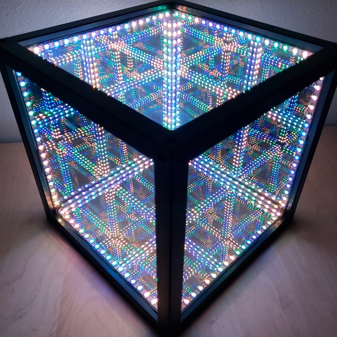
I'm building one of these infinity mirror cubes:

Infinity Mirror Cube

I have some questions regarding the wiring.

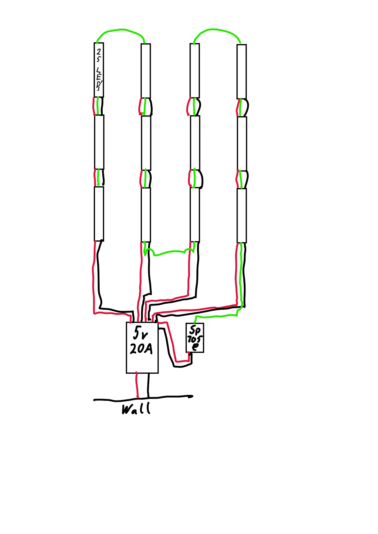
This is what I came up with:

Green is data

Green is data, black is ground and red is 5 V power. Every strip has 18 (not 25 like in the picture) LEDs and will cover one edge of the cube. There are 216 LEDs in total.

The SP105E is an LED controller, I might switch it with an Arduino later. The power supply is 5 V, 20 A (15 A should suffice, but 20 A is much easier to find).

Are there any mistakes?

Additional questions:

  1. From what I read, the wires should be 14AWG or even 12AWG for 5 V, 20 A, but can it be smaller since it's pulling alot less most of the time and is split over 4 strips? How thick should the data wire be? It's going all the way around, but I'm not sure how much current is going through it.

  2. Would an off switch between the wall and power supply work or would something break when I turn it off that way often? What about turning the LEDs off over the controller and then switching the power off?

  3. I'm a bit worried about heat inside the cube, it has 216 LEDs inside a 30 cm cube with infrared reflecting mirrors on all sides (there are some airholes at the top). Does anyone know how hot it might get inside? I'm mostly worried about the glue that holds the mirrors on the frame.

Thank you and sorry if I worded something wrong, English isn't my first language. If you need any more information, please ask.

\$\endgroup\$

1 Answer 1

1
\$\begingroup\$
  • Yes, that should will work. The power doesn't have to flow in the same direction as the data.

  • However, you may get better radio interference suppression (and generate less interference) if you try to run the data next to the ground - this would mean running the green wire from the end of strip 1 all the way back to the power supply, then out to the end of strip 2, instead of taking the shortcut.

    I know this from experience, because I tried shortcutting the data lines in a bigger installation, and whenever a light was turned on or off in the next room, the next several LEDs after the shortcut would randomly change colour (until they received new data from the controller).

    You might also be able to fix it by running an extra ground wire next to the data wire, but I don't know whether that works well. Someone else should know.

  • Make sure to get the LED strips in the right direction for the data flow - of course.

  • The current in the data wire is very small. You can use as small a wire as you want.

  • Since you're dividing the current 4 ways, the current in each power wire is 1/4 of the total current. When it's working. If there's an accidental short circuit, all the power from the power supply might go to one strip.

  • These LED strips only use their maximum power (about 0.25 W each) when they are displaying white at maximum brightness. If you aren't planning to have them display white at maximum brightness all the time, it's okay to plan the cooling based on the average power rather than the maximum power.

  • You can also get away with a smaller power supply if you promise not to set them all to maximum white at the same time. I used this idea to run an LED project off a USB charger (5V 2A).

  • The amount of heat in watts is the same as the amount of electrical power in watts. Not the maximum power, but the actual power at any given time. 216 * 0.25 is 54 watts maximum, and let's say you actually use half that on average, which is 27 watts. I don't think a box this size will have any problem dissipating 27 watts of heat, or even 54. I wouldn't worry about cooling.

    Imagine putting a 60 watt lightbulb inside the box. I think it would get warm, but not hot.

\$\endgroup\$

Your Answer

By clicking “Post Your Answer”, you agree to our terms of service and acknowledge you have read our privacy policy.

Not the answer you're looking for? Browse other questions tagged or ask your own question.