0
\$\begingroup\$

My Rinnai tankless water heater can be connected to a wifi module that controls the recirculating pump and other functions.

The only connection between the PCB of the water heater and the external wifi modules consists of two wires, not polarized.

This powers the wifi module (which does NOT seem to have any battery inside) and allows the controller to communicate with the heater; I believe comm is half duplex only, but I am not 100% sure.

Note: The Control-R manual says: "Additional wiring can run up to 300 feet (91 meters) away from the water heater to ensure a strong wireless signal (18-22 gauge wire is required)" and it's unlikely wireless communication between control box and heater can happen reliably at 91meters.

The only interface I know that uses only two wires for power and comms is 1-wire from Dallas, but I doubt it can deliver enough power for wifi and it is polarized.

What interface/protocol can it be? I am quite surprised

Water heater: Rinnai RUR199i Wifi Controller: Rinnai Control-R

https://i.sstatic.net/V5xoj.jpg

  • It seems input comes through a MDB8S full bridge rectifier to provide power
  • On top there is also a MX30LF2GE8AB-TI 2Gbit NAND
  • The main chip, that also provides wifi, is a MediaTek MT7620
  • The chip uses external DDR (wow, check the DDR routing on the PCB, so much work) Winbond W971GG6SB-25
  • The back has a ZigBee section, with SiGe2432L frontend, EM357 chip and MX25L8006E - what is it, memory?; I know there are RINNAI accessories that connect with ZigBee that can connect to this module, like a button, sensors to detect presence; I do not know if this is also used to talk to the heater.
  • There is also a chip marked R5F101JED that seem to be a microcontroller

EDIT 2: I checked the PCB again and yes, the inputs are decoupled with some caps, then go to the following "mystery" component (looks like some sort of daughter board?) and finally to the R5F101 microcontroller. Any idea what is the yellowish thing?
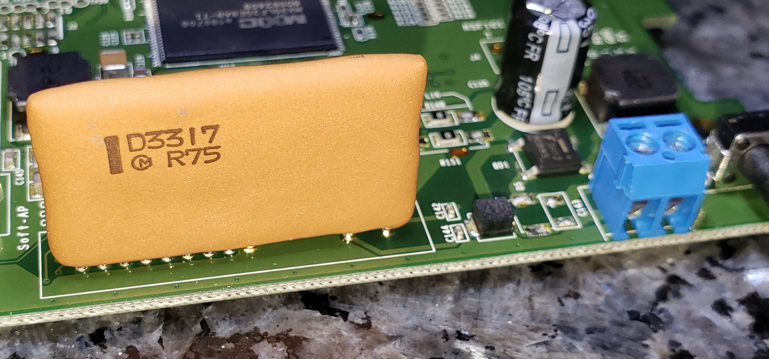
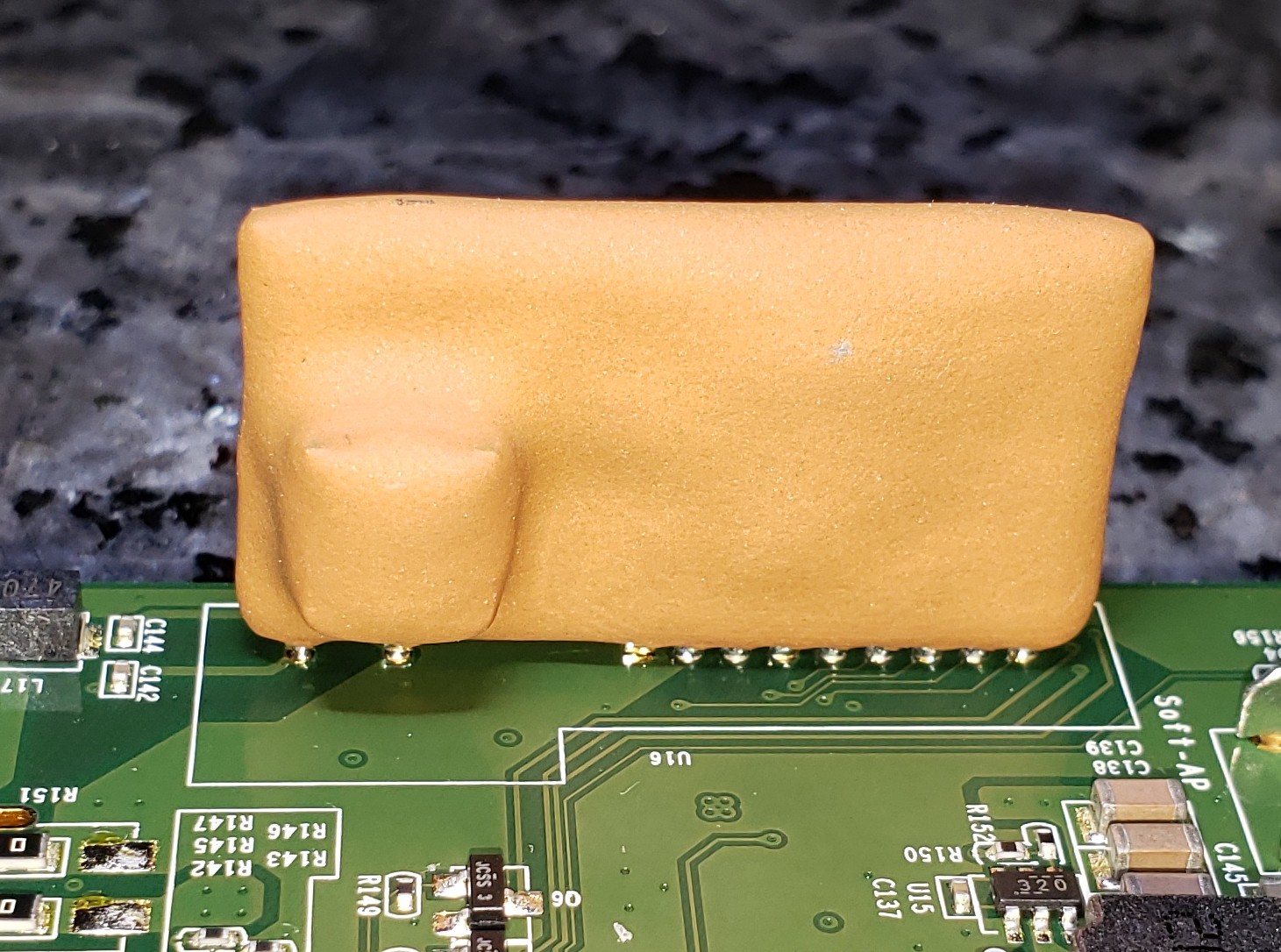
enter image description here enter image description here

\$\endgroup\$
3
  • \$\begingroup\$ There are many candidates, could be something custom branded that you won't get it. A similar communication is Lonworks or some powerline modem. The Lonworks is easily discovered, since it uses propiteary ASICs you could see the chip inside the electronics. You could post some pics, since nobody could guess what's inside. \$\endgroup\$ Commented Jul 26, 2020 at 21:08
  • \$\begingroup\$ @MarkoBuršič fair, I have added a link to an IMGUR album with detail photos of the PCB of the controller (the PCB inside the water heater is much more complicated to photograph in detail) \$\endgroup\$ Commented Jul 26, 2020 at 22:41
  • \$\begingroup\$ The PCB is a kind of gateway ZigBee <-> Ethernet, so the heater's Wifi module is actually a Zigbee TRX that uses power supply and sends half duplex data over two wires , similarly as answered by other user, AC coupled data over DC power. \$\endgroup\$ Commented Jul 27, 2020 at 7:22

2 Answers 2

2
\$\begingroup\$

I am interested in exact same answer and I have exact same setup. The reason is their Rinnai's wifi module is complete mess due to bad WIFI and bad mobile app implementation. If I could reverse engineer their protocol, I would like to replace their system with Raspberry Pi 4 or ESP32 design. I thought it was simple UART serial but it looks like more customized type of protocol.

yes, I think it is half duplex or something really slow. when you pull heater stats, it is horribly slow.

see here: https://github.com/ayavilevich/rinnai-control-panel-sigrok-pd

It may be PLC communication and they have used sigrok on Rinnai control panel. I am assuming WIFI module uses the same PLC protocol.

\$\endgroup\$
13
  • \$\begingroup\$ Hi, I have received a new module from Rinnai because the previous one wouldn't connect to the Ayla "cloud" servers (I setup a rogue AP and captured the traffic incoming from the old module, I figured there was some problem with the certificates but that is not a concern as the new unit connects correctly). As you explained, the system is useless anyway because the app fails misteriously. I can just change the temperature (which is annoyingly only presented in F degrees even if I set my heater in C) but not start the recirculation that is the most important feature I was aiming for. \$\endgroup\$ Commented Aug 17, 2020 at 6:32
  • \$\begingroup\$ Oh, I am pretty sure it uses the same as the non WiFi control panel, as the two devices are interchangeable... That program looks pretty interesting. I was thinking to use an ESP32 too.. \$\endgroup\$ Commented Aug 17, 2020 at 6:36
  • \$\begingroup\$ yes, the only reason I needed app for re-circ and scheduling.. after lot of trial and error, I finally figured about re-circ. Scheduling is probably still broken and every app update breaks something that works. \$\endgroup\$
    – vkdelta
    Commented Aug 18, 2020 at 18:15
  • \$\begingroup\$ Hello @vkdelta, I am now exchanging ideas with the author of the git you linked to get more information about this protocol. He published a VERY nice article about it: blog.yavilevich.com/2020/08/… However, his heater does not have a recirculation pump, so I'll have to figure out the details about that. Can you tell me how you fixed the recirculation on the Control-R and the app? I'd like to start the recirculation on demand. What settings did you use on the heater? In particular 04 (recirculation settings) and 05 (recirculation mode) \$\endgroup\$ Commented Aug 18, 2020 at 18:40
  • \$\begingroup\$ @AlessioSangalli It looks like this is brand new article. I contacted him via email last weekend but have not got time to followup yet. I have RuR199iN .. I am guessing you have same or similar as it is standard in new builds (at least for SF bay Area) .. there are few stupid peculiarities with the app vs Module (such as no double NAT if you have 2 routers but works from external Public IP, etc). here are my settings which I captured in video.. see if this helps you.. 4B and 5A .. dropbox.com/s/uqhgkhpexee7ckq/IMG_2252.mov?dl=0 \$\endgroup\$
    – vkdelta
    Commented Aug 18, 2020 at 23:46
0
\$\begingroup\$

It is pretty simple to design a system that shares data and power wires -- all you need is inductors so separate out DC component (for power) and capacitors for AC component (for signal).

Unfortunately, such system requires a data protocol that can work over capacities link... which means most of the common protocols (UART serial, I2C, onewire, CAN) are not going to cut it. One would need to design a custom protocol for this -- this is can be pulse duration, MFM, or something else.

For an example of a design, see TI's SLLA336 appnote: https://www.ti.com/lit/an/slla336/slla336.pdf . Take a look at Figure 5 for an input stage, I'd expect your board to have something similar.

Note that most likely, your heater DOES NOT USE exactly the same protocol as SN65HVD96. Most likely it is a custom implementation to save costs. You will need to scope the wires and see!

\$\endgroup\$
2
  • \$\begingroup\$ OK about attaching a scope to it: what would be the correct procedure? The water heater is grounded not only though the ground in the receptacle but also through water and gas pipes, so it's pretty much impossible to float it, even with an isolation transformer. It sounds like I'll have to float the scope? \$\endgroup\$ Commented Jul 27, 2020 at 6:25
  • \$\begingroup\$ I have edited my question with a couple of pictures of what might be the electric interface for this protocol. Do you have any idea why that circuit would be such an odd shape? \$\endgroup\$ Commented Jul 27, 2020 at 8:39

Your Answer

By clicking “Post Your Answer”, you agree to our terms of service and acknowledge you have read our privacy policy.

Not the answer you're looking for? Browse other questions tagged or ask your own question.