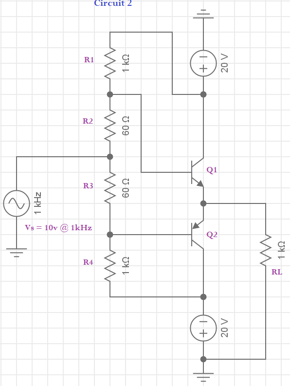
EDIT: I realize that the original circuit is deeply flawed and will burn up upon re-entry. Thanks to anyone who can help me understand why!
I'm learning to analyze Class AB amplifiers, but haven't found a good source with information on how to determine their input impedance. I built this circuit as an example. It's a simple Class AB amplifier with resistors to overcome crossover distortion. I would love feedback on whether my understanding of \$R_{in}\$ is correct. I assumed both transistors have a \$\beta=50\$.
As far as I can tell, \$V_S\$ will see two branches: first, it will see the \$60\Omega\$ R2 in series with the parallel combination of R1 and the impedance looking into the base of Q1; in the other branch, it sees \$60\Omega\$ from R3 in series with the parallel combination of R4 and the base of Q2. So an equation like the following should work, yes?
$$R_{in}=(R_2+(R_1||R_{ibQ1}))||(R_3+R_4 || (R_{ibQ2}))$$
I started with the Q1 branch. First I found \$r_e\$. \$I_C\$ fluctuates between 2.6mA and 2.7mA, giving a very small value for \$r_e=25mv/2.6mA=9.62\Omega\$. With this in mind I can solve for \$R_{ibQ1}=\beta*(r_e+R_L)=50*(1000+9.62)=50,481\Omega\$. \$R_{ibQ1}\$ is in parallel with R1 and that combination is in series with R2, so the entire Q1 branch of the circuit is $$R_{Q1branch}=60\Omega+(1000\Omega||50481\Omega)=1040\Omega$$
From here I'd like to think it's as easy as imagining the Q2 half of the circuit as equivalent in impedance. The total input impedance of the circuit, then, is half of the previous calculation, or \$R_{in}=1040||1040\Omega = 520\Omega\$
I'm sure this isn't exactly correct, as it seems way too simple to only solve half the circuit. I'd love to hear all the ways I've been led astray. Please note that this is not an amplifier I imagine has any real purpose, just one that works enough to help me understand how to analyze its input impedance.

