1
\$\begingroup\$

enter image description here

Hello,

I have a circuit that I designed myself. In summary, I feed the circuit with 2 CR2032 type batteries and try to get 3.3 V output from the LD1117 type regulator. However, I get 4.7 V output from the regulator. I also observe a drop in battery voltage, interestingly when I feed it on battery. By voltage drop, I mean it happens instantaneously, maybe it would be more correct to specify it as voltage loss.

Let me share with you the situations I have examined.

There was no change of state when I first connected parallel capacitors to the circuit. edit: I mean 10uf and 100nF(capacitors on the datasheet)

I tested the battery packs and batteries also out of circuit. There is no problem with them either.

When I set the same regulator up to the bluepill supply in the breadbord and tried to supply it without capacitor, I got a constant 3.3V output. However, when I supply the circuit with DC supply 6V from the outside, I constantly get 4.7V from the regulator output. And when I feed it with the battery, it initially comes to 4.7 in the same way, then the voltage of the batteries starts to decrease in a short time. When I deactivate, their voltage comes back to 3V.

I haven't had the opportunity to test it yet, but I'm thinking about the question of whether reverse current is coming from somewhere. Do you think putting a diode on the regulator output can solve it? I am open to your suggestions, thanks in advance.

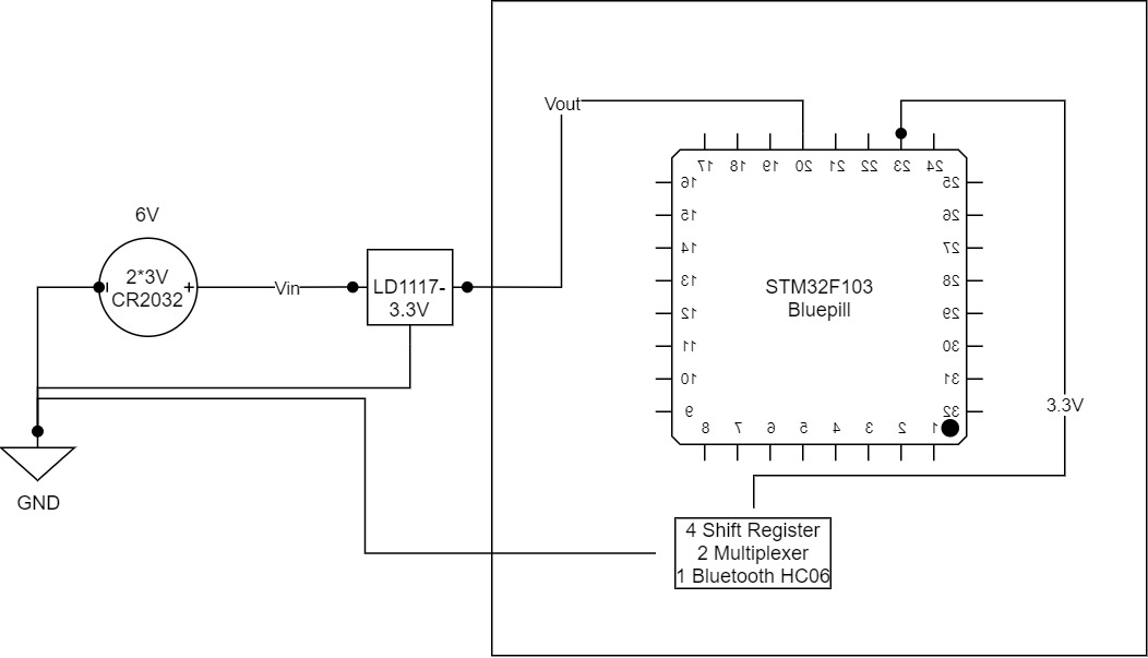
\$\endgroup\$
11
  • 3
    \$\begingroup\$ The datasheet Figure 4 shows 100 nF on the input and 10 uF on the output. Your schematic doesn't. Did you feel that they were optional? ;^) \$\endgroup\$
    – Transistor
    Commented Sep 18, 2020 at 20:01
  • \$\begingroup\$ As I said "There was no change of state when I first connected parallel capacitors to the circuit." I also tried adding capacitors to the circuit, but it did not change :/ \$\endgroup\$
    – magnesian
    Commented Sep 18, 2020 at 20:16
  • \$\begingroup\$ OK. Just checking all the silly stuff. The pinout is 1, 2, 3: GND, Vout, Vin. Nothing mixed up there? \$\endgroup\$
    – Transistor
    Commented Sep 18, 2020 at 20:22
  • \$\begingroup\$ Give it some dummy load with a resistor. \$\endgroup\$
    – winny
    Commented Sep 18, 2020 at 20:29
  • 1
    \$\begingroup\$ By "connect ~100 ohm into Vin" I presume you mean you connect it in series between the 6 V source and the regulator input. With a 6 V supply and a 100 ohm load the max current you could get would be 60 mA. It sounds as though you have connected a 100 ohm resistor across the 6 V battery. How about a good sharp, well cropped photo of your setup? \$\endgroup\$
    – Transistor
    Commented Sep 18, 2020 at 21:35

1 Answer 1

0
\$\begingroup\$

I think the problem has been solved as of yesterday. I noticed a voltage of about 30mV in the ground of my circuit board. For the same reason the regulator seems to be raising the voltage above 3.3 by taking the ref voltage. I think this is caused by the ground touch of one of the solders I made on the circuit. Because I did not have a problem with my other pcbs with the same feature. Thank you 👍

\$\endgroup\$

Your Answer

By clicking “Post Your Answer”, you agree to our terms of service and acknowledge you have read our privacy policy.

Not the answer you're looking for? Browse other questions tagged or ask your own question.