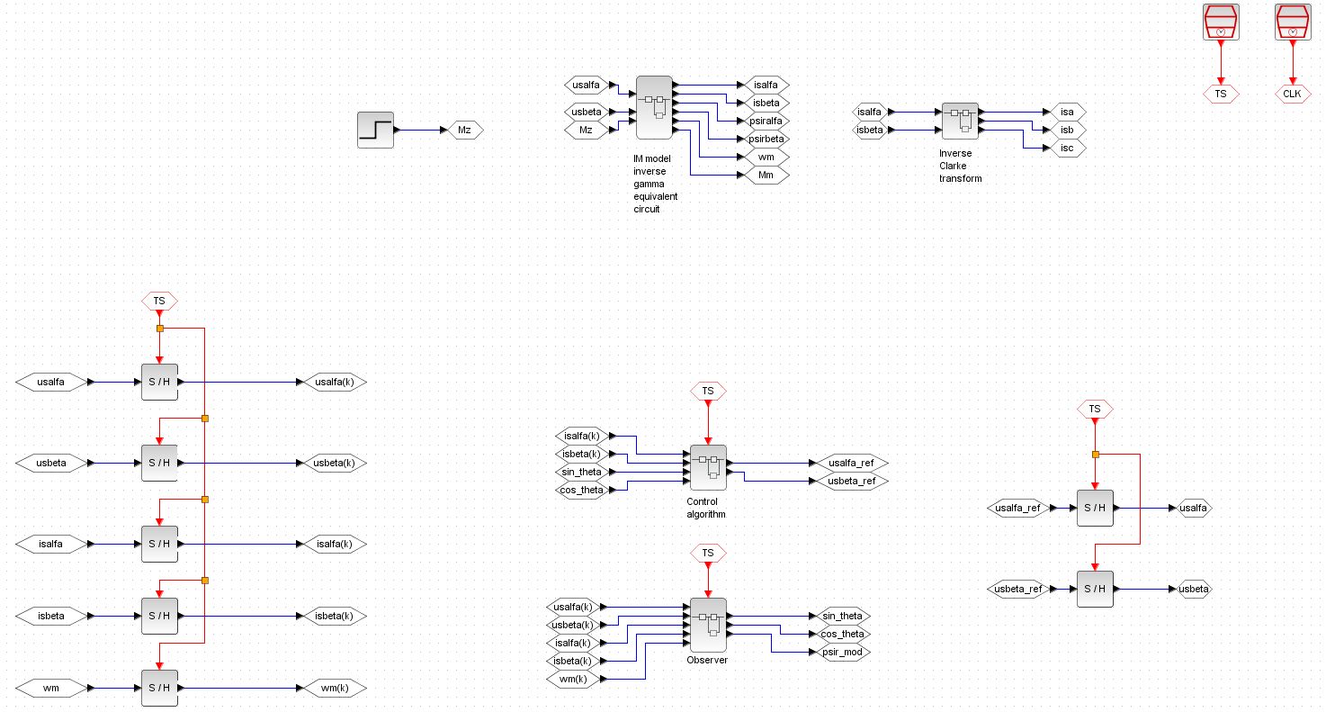
I have been developing a simulation of the field oriented control of the three phase induction motor. The simulation is developed in the Scilab/Xcos (v5.5.2) which is a free of charge Matlab/Simulink like software. The diagram of my simulation in the Xcos toolbox looks like this
As you can see the simulation basically consists of below mentioned main blocks:
IM model
Dynamic model of the three phase induction motor
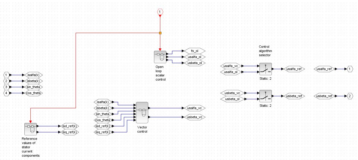
Control algorithm
Produces components of the reference stator voltage in the stationary reference frame based on chosen control algorithm (open loop scalar control x field oriented control)
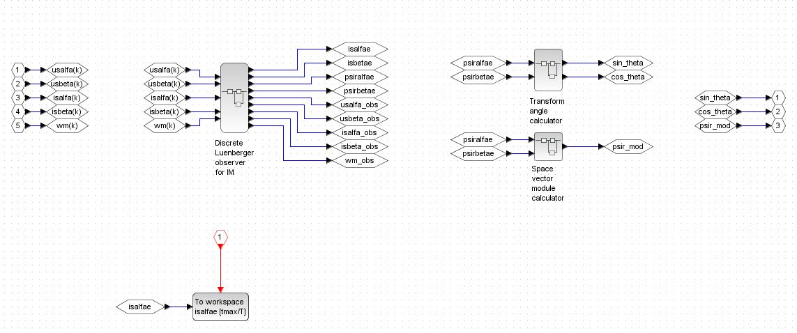
Observer
Calculates estimate of the components of the unmeasurable rotor flux and based on that calculates orientation of the space vector of the rotor flux for the field oriented control algorithm
The block a) is a continuous time domain system and the blocks b) and c) are discrete time domain systems (they model software). Due to that arrangement the blocks b) and c) are separeted from the continous world (plant domain) via the ADC converter (modeled via sample and hold blocks) at their inputs and via the DAC conveter (first order hold algorithm) at their outputs.
The simulation has been developed in two steps:
induction motor controlled via open loop scalar control algorithm
Simulation works correctly because no feedback is present
induction motor controlled via field oriented control algorithm
At first I have encountered a problem with the algebraic loop error
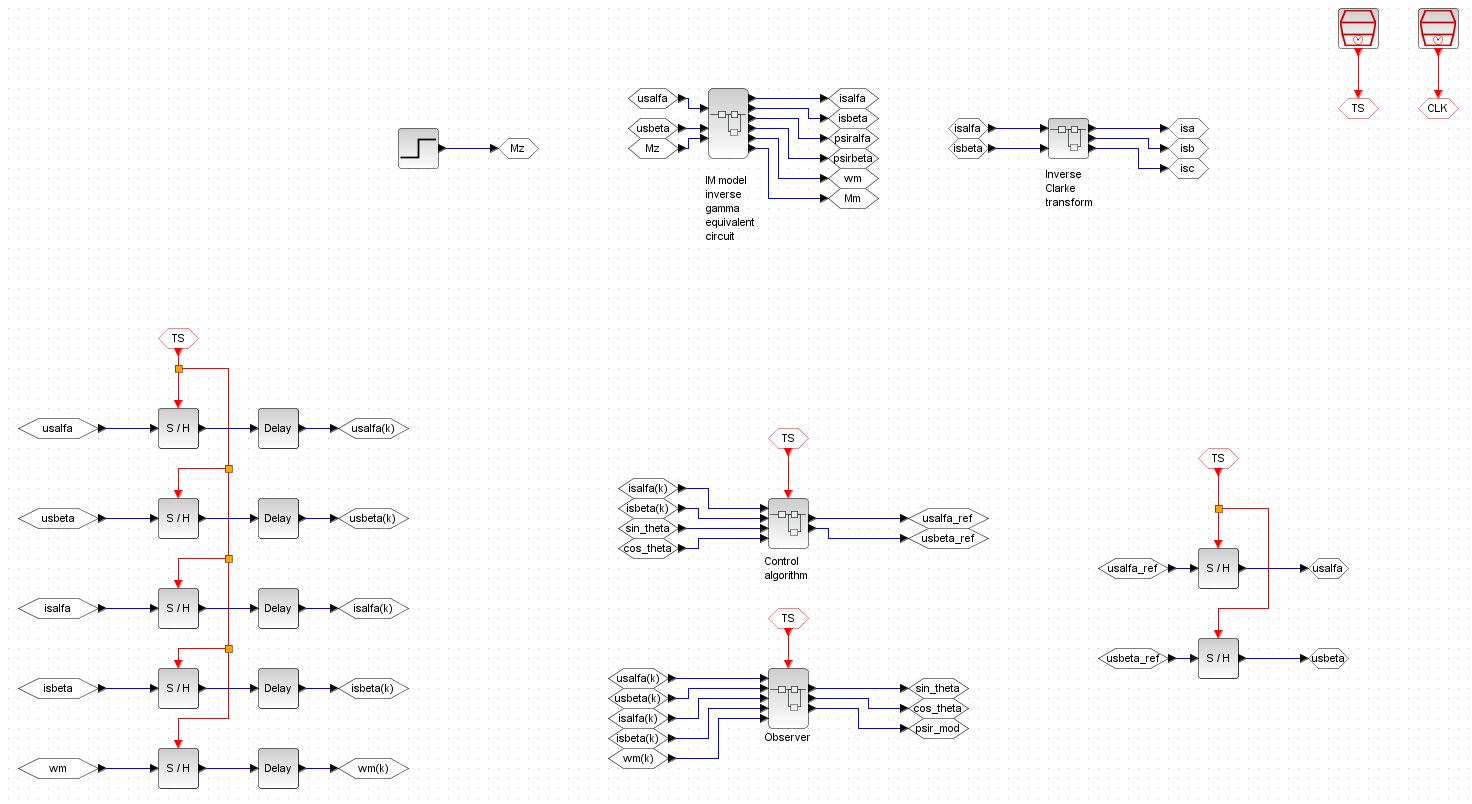
Based on my experience with the Matlab/Simulink I have inserted a time delay into the control loop (please see the blocks "Delay" in the ADCs part)
I have set the delay of these blocks to a small fraction of the sampling period (\$T_s = 0.0001\,\mathrm{s}\$ and the delay has been set to \$0.1\cdot T_s\$). Insertion of that delay has resolved the problem with the algebraic loop but it has also caused two unwelcome facts. Firstly the state estimation error in the observer is high despite the "small" value of the delay. Secondly the delay insertion caused huge increase of the simulation time.
I have also thought about simulation diagram rearangement to avoid the algebraic loop inherently but I can't see any way how to do that - ultimately I simulate the feedback loop.
Does anybody have any idea how to split the algebraic loop in such a manner which does not corrupt the state estimation process in the observer and also does not increase the simulation time too much?


uas input as well as a copy of the plant outputyas another input. If all of these (usalpha,isalpha,wmetc.) are delayed equally and fed to an observer, why would it have any effect on the estimation error ? Is the estimation error computed by comparsing to true value which, to be fair, should also be delayed if used for comparison with an observer running with a delay ? \$\endgroup\$