4
\$\begingroup\$

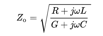
The formula for the characteristic impedance is below enter image description here

So the characteristic impedance is a complex number. But why is a complex termination generally not used?

With complex termination I mean a transmission line terminated by more than just a resistor. Maybe a resistor and a capacitor.

\$\endgroup\$
1
  • \$\begingroup\$ A less complex designation could be non-resistive termination. \$\endgroup\$ Commented Dec 27, 2020 at 19:39

2 Answers 2

11
\$\begingroup\$

So the characteristic impedance is a complex number. But why is never a complex termination used?

When \$j\omega\$ is significant, the formula reduces to this: -

$$Z_0 = \sqrt{\dfrac{j\omega L}{j\omega C}} = \sqrt{\dfrac{L}{C}} = \text{resistance}$$

This applies pretty much to frequencies of 1 MHz and greater i.e. the vast majority of RF applications.

At audio frequencies, the equation becomes more complex and is usually approximated to this: -

$$Z_0 = \sqrt{\dfrac{R}{j\omega C}}$$

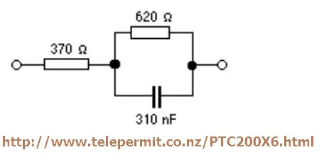
So, for telephony applications, a complex termination method is used (in order to reduce telephone side-tone) like this: -
enter image description here

New Zealand and the UK use the above complex impedance for terminating a telephone cable in order to optimize the anti-side-tone circuit. Other countries use similar but not identical values.

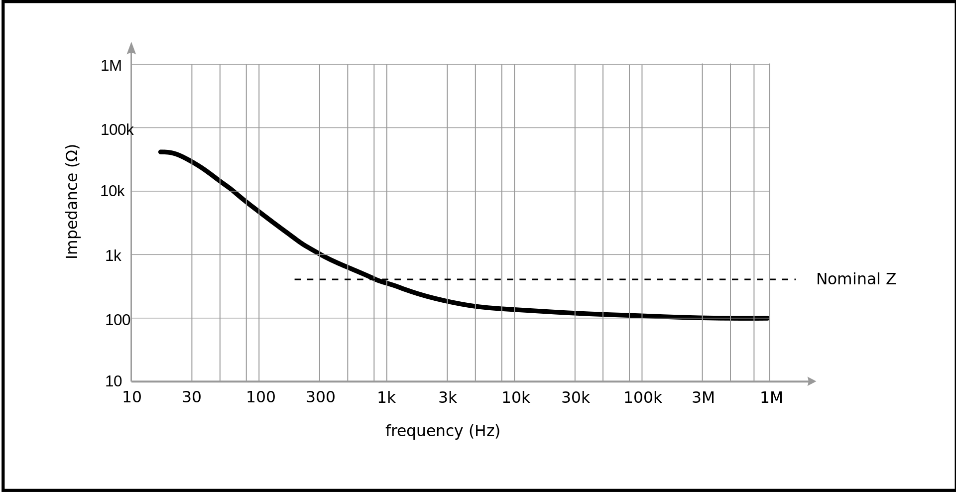
Generally, a cable will exhibit this type of impedance response: -
enter image description here

At DC (well, 30 Hz) the impedance is determined by the ratio \$\sqrt{\frac{R}{G}}\$ and if R = 1 Ω then, according to the above (taken from wiki), \$\frac{1}{G}\$ has to be 1.6 GΩ and this wouldn't surprise anyone I would think! But, it all gets a little messy at mid-band audio and up to about 100 kHz for most cables.
\$\endgroup\$
2
  • \$\begingroup\$ Thanks again. You wanted to add a picture that might help for the microcap installation. Could you please notify me if you do? \$\endgroup\$
    – Yoomo
    Commented Dec 26, 2020 at 15:25
  • \$\begingroup\$ @Yoomo I added it to the bottom of my previous answer on TDR. It wasn't for installation; it was for how to set up a transmission line. I can't help with the install. \$\endgroup\$
    – Andy aka
    Commented Dec 26, 2020 at 15:29
5
\$\begingroup\$

When designing an transmission line, we typically want to make \$R\$ and \$G\$ as small as possible such that they are negligible.

If \$\omega L\$ and \$\omega C\$ are much larger than \$R\$ and \$G\$, then things simplify:

$$Z_0 \approx \sqrt{\frac{j\omega L}{j\omega C}} = \sqrt{\frac{L}{C}}$$

The characteristic impedance becomes entirely real as a result, meaning the termination can then be acheived with a simple resistor.


Bear in mind this is just an approximation. It is not possible to completely zero \$R\$ and \$G\$, making all real transmissions lines have a small imaginary component. However this imaginary component is usually small enough that practical circuits will still function without a perfect match.

For very high frequencies or very low frequencies, we tend to include matching components such as transmission line stubs or series and parallel reactive components to transform the imaginary component to a real component over a limited frequency range of interest.

\$\endgroup\$
2
  • \$\begingroup\$ So there is no such thing as a complex transmission line? \$\endgroup\$
    – Yoomo
    Commented Dec 26, 2020 at 14:53
  • \$\begingroup\$ @Yoomo One with significant R or G would have complex impedance, so it can exist. \$\endgroup\$
    – Hearth
    Commented Dec 26, 2020 at 14:53

Your Answer

By clicking “Post Your Answer”, you agree to our terms of service and acknowledge you have read our privacy policy.

Not the answer you're looking for? Browse other questions tagged or ask your own question.