Why do we not see this decaying sinusoid every time the switch switches - that should be like applying a step input to the filter each time, correct?
While it is a step-like action, the time constants differ by a very large amount. The step response of the (R)LC filter is dictated by its natural frequency, which is much lower than the switching frequency. Simply put, you're looking there at ms worth of time, while the pulse width is less than 10 µs. Plus there are other factors at play.
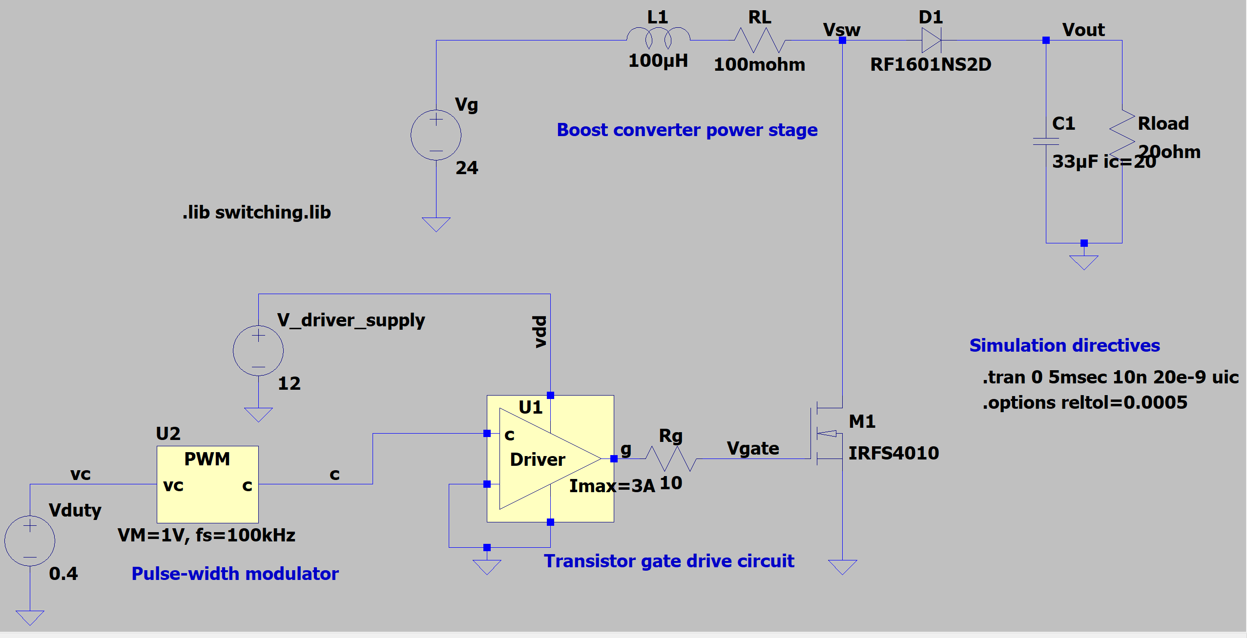
Can someone explain to me where the initial transient response is coming from
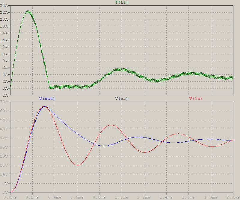
First, you chose an interesting combination of values. If you look at the trace for the inductor current, you'll see that it starts in CCM, but then it goes into DCM immediately after the first peak, only to continue in CCM afterwards. This complicates things a bit.
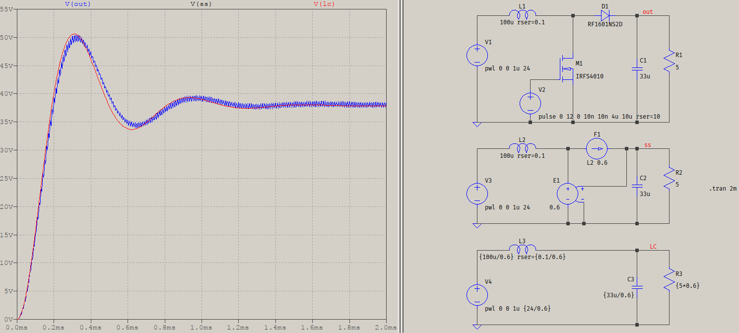
As it is, the whole power stage can be simplified to be an RLC filter, with modified values according to the duty cycle. The ideal CCM transfer function for the boost converter is \$M=\dfrac{1}{1-\alpha}\$ which, for your value of 0.4, it means 1.67 times the input voltage. The inductor will charge with energy during the ON time, and release it during the OFF time (as opposed to all the time, like a mains transformer). The capacitor, too, while the load will be proportional to M. In addition, modelling the input source to be a step source of 24 V times M, will result in the following equivalent circuit:

The upper one is your circuit (V(out), blue), the middle one is a small-signal model (V(ss), black), and the bottom one is the RLC equivalent (V(LC), red). If you can't see the black trace it's because it overlaps with the red trace. There are small differences between the switched waveform and the rest due to the MOSFET's and diode's ON/OFF resistances & co.
Now, because of the mix of modes that your initial values presented, I had to choose a different value for the load (5 Ω), to ensure CCM everywhere. Otherwise it would have looked like this:

As you can see, the waveforms (almost) coincide until the DCM part; then, all bets are off. The small-signal model can be adapted to the situation, which would require some conditionals, but the RLC circuit is linear.
when do we consider the time-domain response of the LC filter?
This question is very vague, and impossible to answer. You'll have to decide what you really want to know.
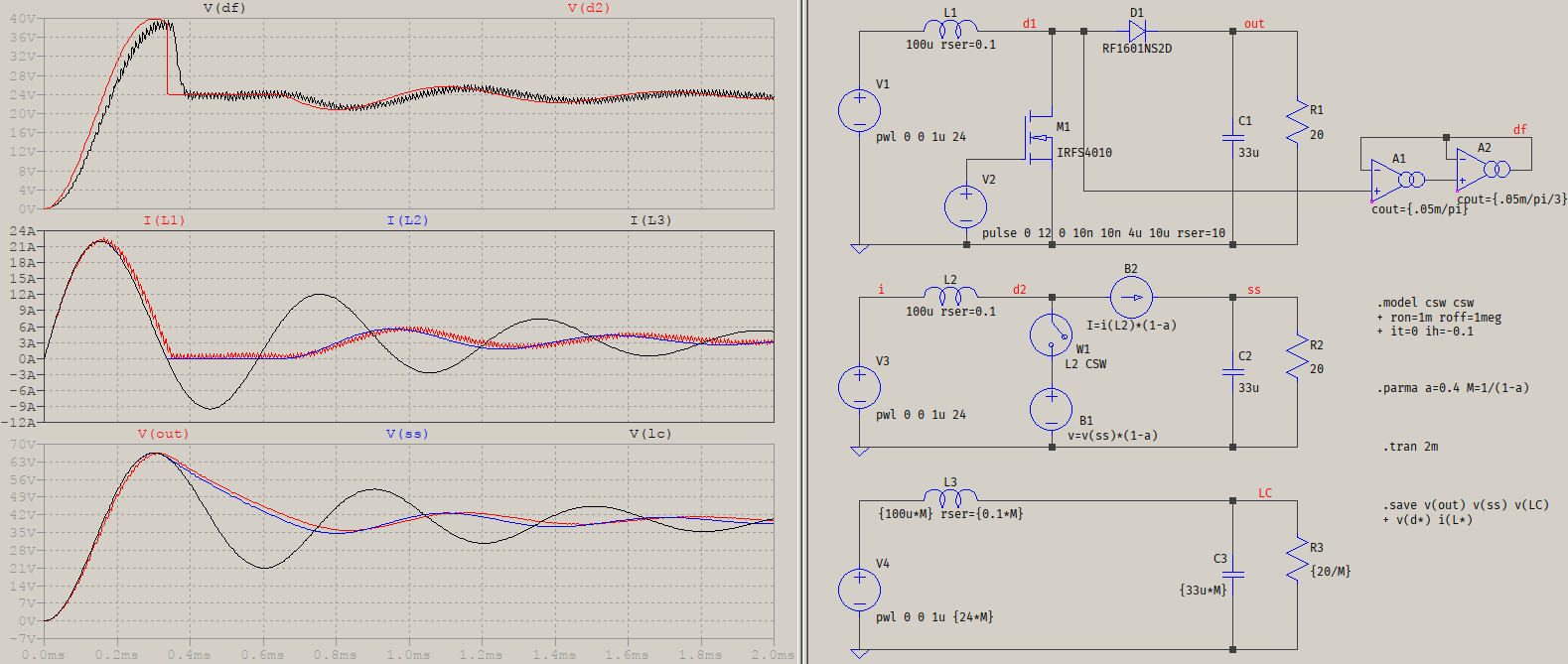
I've modified the small signal model to include DCM operation, so now it is apparent that the DCM operation is nonlinear and, thus, the simple RLC approach is unsuited:

W1 disconnects B1 when the current through L2 drops below zero, so it appears that the equivalent drain voltage is open. A1 and A2 form a Bessel lowpass to filter out the switched drain voltage of M1, showing in the upper plot pane the comparison of the average of V(d1) (with a slight delay due to the filter) with V(d2), which is the small-signal equivalent. Since a time-varying resistor is involved, there cannot be a linear equivalent of the circuit with an RLC only.
The conclusions remain (as mentioned in the comment below):
- the undamped response is because the overall transfer function of the converter (without feedback) is largely dominated by the output LC filter and the equivalent resistance/impedance as the load, thus the switched mode step response can be replicated by an equivalent linear RLC circuit, as long as there is no DCM involved.
- the switching, itself, is just like applying a step, each time, but the duration of that step is very small compared to the period of the natural frequency of the filter.


