0
\$\begingroup\$

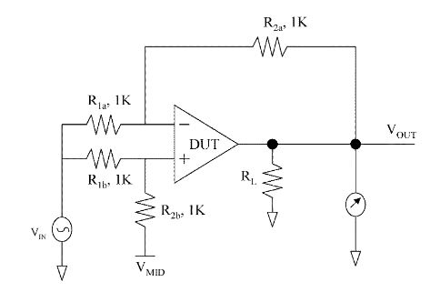
I am trying to calculate the CMRR of following circuit. I am aware that similar circuit has been posted here before but I have read through them and they don't answer my question.

enter image description here

Based on my research so far, this circuit is one of the way to measure the CMRR of op-amp assuming that the resistor values for \${R}_{1a}\$, \${R}_{1b}\$, \${R}_{2a}\$,\${R}_{2b}\$ match perfectly.

In this circuit, i assume that the common mode input \${V}_{CM}\$ is \$ {V}_{IN} \frac{{R}_{2b}}{({R}_{1b} + {R}_{2b})} \$

And I learnt that the \$ CMRR = \frac{Differential-mode-Gain}{Common-mode-gain} \$. So, normally, i would find the common mode gain \$ {A}_{CM} \$ and differential mode gain \$ {A}_{DM} \$ separately.

However, i noticed, in most of the online sites, they simply measure the \$ \frac{{V}_{out}}{{V}_{in}} \$ and considered it as \$CMRR\$

My Question is: Why is the \$ \frac{{V}_{out}}{{V}_{in}} \$ of this circuit is equivalent to the \$ CMRR \$ of the circuit?

Can someone point me in the right direction?

EDIT 1:

I have added some link to the similar questions per @MarcusMuller request.

operational amplifier CMRR measurement

This question was asking what is the correct common mode input voltage. I am well are that it is \$ {V}_{IN} \frac{{R}_{2b}}{({R}_{1b} + {R}_{2b})} \$ so it doesn't help me.

Op Amp CMRR problem

This question was asking about his particular issue regarding common mode gain.

\$\endgroup\$
5
  • \$\begingroup\$ Ok, as you say there are other similar questions, can you link to the things you've read already? And explain how they are not answering your question? Otherwise, we'll just be giving the same answers again, wasting our times. And we don't like that. (also, that circuit won't work well with opamps that were designed after ca. 1980. And won't work well with real resistors. In all honesty, this circuit simply won't work. It tries to measure an imperfection of an opamp by ignoring all imperfections.) \$\endgroup\$ Commented Dec 30, 2020 at 17:47
  • \$\begingroup\$ For example, for the LM324, released in 1972 (That's nearly 50 years in the past!!) I can't find a single manufacturer datasheet that specifies a CMRR of less than 65 dB – do you realize how small \$V_{IN}\$ must be if \$V_{OUT}=10\,\text{V}\$? Can you reliably measure that? How exact are your 1 kΩ resistors? 0.1%? What does \$R_{1b}=0.999\,\text{kΩ}, R_{1a}=1.001\,\text{kΩ}\$ do to your \$V_{OUT}\$, even if the DUT has perfect CMRR? \$\endgroup\$ Commented Dec 30, 2020 at 18:01
  • \$\begingroup\$ @MarcusMüller I didn't include the links or explain why they are different because while they were using the same circuit, their questions were different (we are asking totally different things). I understand that this circuit is more theoretical than practical, but i am just trying to gain some understanding at theoretical level why this can be done. I have added some similar link anyway per your request. \$\endgroup\$
    – estudent21
    Commented Dec 30, 2020 at 18:03
  • \$\begingroup\$ Effectively that will only measure the resistor mismatch. Circuits for measuring CMRR must eliminate that as a source of error. \$\endgroup\$
    – user16324
    Commented Dec 30, 2020 at 18:04
  • \$\begingroup\$ @estudent21 problem is that I simply have to "bend" theory until that formula works that it doesn't make sense to me any more – I don't think it's possible to really argue for CMRR=Vout/Vin, honestly, because one would have to write down a lot of assumptions before one comes to that conclusion, and some of them would simply be wrong. So, sorry, can't prove something that's wrong. Which "online sites" are you referring to, and are they trustworthy? \$\endgroup\$ Commented Dec 30, 2020 at 18:18

2 Answers 2

2
\$\begingroup\$

To put it shortly, even if you had perfect resistors (and resistors aren't perfectly matched, so this won't even remotely work), the formula as stated is wrong.

You need to vary the input voltage and observe the variation of the output voltage; the ratio of these two differences would then be the CMRR.

Again, it's not \$\text{CMRR}=\frac{V_{out}}{V_{in}}\$; it'd be \$\text{CMRR}=\frac{\Delta V_{out}}{\Delta V_{in}}\$, because that's how much a variation of common mode input gets amplified (that's literally just the definition of amplification applied to CM input).

And again, that assumes that your resistors are all perfectly matched, which they aren't. The best resistors I can buy are 0.01% accurate, which means the differential gain isn't exactly 1, but has some unknown error, and that sadly doesn't cancel, and at CMRR > 60 dB (which is pretty boring compared to what modern opamps offer), that error by far outshines our CM amplification. You'd hence need to measure that error, too, which, again, is pretty hard, because your measurement process needs to change the system much less than the CMRR, and measuring voltages does actually draw a bit of current.

\$\endgroup\$
1
\$\begingroup\$

The Op-Amp has an internal CMRR far better than any R tolerance. Yet the R tolerance error defines the output for ideal parts leaving only the Acm to have some value. Thus the CMRR of the circuit is simply \$V_o = A_{dm} * V_{dm} (=0) + A_{cm} * V_{cm} , ~~~or ~~ A_{cm}=V_o/V_{cm}\$.

Let the worst-case R tolerance error =X% for all 4 parts, thus degrades the Op Amp's CMRR = Adm/Acm = 4 * X% and thus the DM gain makes the CMRR even worse which demands precision-matched R ratio components and similarly matched wire impedance or STP cable for EMC concerns. I'll let you prove this as it was not part of your question.

\$\endgroup\$

Your Answer

By clicking “Post Your Answer”, you agree to our terms of service and acknowledge you have read our privacy policy.

Not the answer you're looking for? Browse other questions tagged or ask your own question.