0
\$\begingroup\$

I am putting together a circuit board that is supposed to do its own power regulation. I need to convert 120VAC to ~5VDC. Due to the very limited real estate on the PCB, I would rather not use transformers. With some research, I was able to find two different circuits that can achieve this conversion without the need for a transformer.

The first circuit utilizes a primary-side regulator and has an offline buck topology. From the datasheet, the circuit looks like this: enter image description here

Datasheet of the regulator

The second circuit does not have a regulator, but rather a full-bridge rectifier. The circuit looks like this: enter image description here
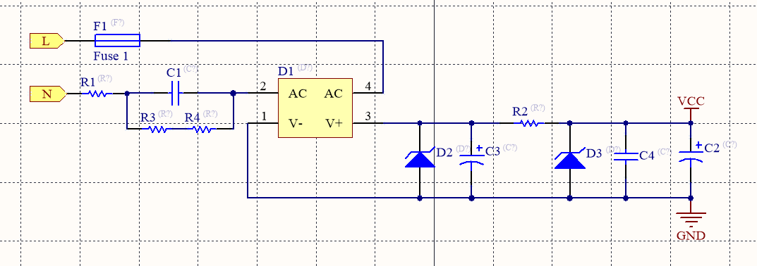
Datasheet of the rectifier

The output I am aiming for should be around ~5 V (although the output of the converter will be run through an LDO regulator) and a current of at least 50 mA.

My question is, what would be the pros and cons of using either of them? I am guessing the latter could be less efficient, however has fewer components and no ICs, it will be cheaper and would require less area on a PCB. Would that make it a better option?

\$\endgroup\$
14
  • 4
    \$\begingroup\$ External wall wart. Neither of these provides isolation from the mains supply, so they must both be isolated from anything you can touch, and the second will malfunction dangerously if GND connects to the mains GND. \$\endgroup\$
    – user16324
    Commented Jan 2, 2021 at 22:15
  • \$\begingroup\$ @BrianDrummond this will all be implemented on a PCB and will be housed in an enclosure, so I am not very concerned about physical contact. But what I guess you're saying is if the rectifier fails and shorts the mains GND to internal GND that would be a hazard? \$\endgroup\$ Commented Jan 2, 2021 at 22:25
  • 2
    \$\begingroup\$ C1 needs to be quite large in the second design, it's hard to say which will be smaller. \$\endgroup\$ Commented Jan 2, 2021 at 23:28
  • 2
    \$\begingroup\$ @aeroengineer in schematic 2, if circuit ground is connected to mains ground and/or neutral, C1 is bypassed. Definite hazard. It would be much safer to have C1 and associated resistors on the Line side, rather than Neutral side. \$\endgroup\$ Commented Jan 3, 2021 at 16:25
  • 1
    \$\begingroup\$ The net you label GND on your schematic can never be allowed to be exposed to human touch, nor can it be interconnected to any other electrical circuit that uses a different ground except through galvanic isolation. Also, your "GND" needs to be insulated the same way that the line needs to be insulated to prevent shock hazard. This makes it impractical for most uses, but since I don't know what your load is, I reserve judgement. I am just trying to alert you to a serious potential safety hazard that two other people also mentioned in the comments. \$\endgroup\$
    – user57037
    Commented Jan 3, 2021 at 20:18

2 Answers 2

3
\$\begingroup\$

I am guessing the latter could be less efficient, however has fewer components and no ICs, it will be cheaper and would require less area on a PCB.

Yes it is far less efficient and yes it has fewer parts, but it may not be cheaper and probably won't take up less space. The only real advantages are that it uses generic parts that may be easier to source, and the design is less critical.

C1 must be rated for AC mains operation, so it will be much larger than an MLCC or electroytic type. According my calculations around 2.2 μF is required to get 50 mA at 5 V. At best (full load) the circuit could be around 60% efficient, but with no output it will consume almost double the power (since it has to absorb the current that would otherwise go to the load). This is very wasteful if the device spends most of its time in standby, as well as creating extra heat that may be hard to get rid of in a small enclosure.

The MP158 design needs 2 more components, but they are small compared to the size of the mains rated capacitor required for the second circuit. If you use a bridge rectifier then C1 can be even smaller. This circuit is much more efficient and draws minimal power on standby, so it should run a lot cooler.

Support components for the MP158 must be carefully chosen for proper operation, and the PCB layout is critical. However if you stick close to the recommended values and layout in the datasheet you should be OK. Obtaining supplies might be an issue (Mouser say it is 'obsolete'). You might consider using a later equivalent such as the MP173A.

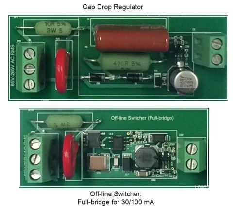
To get some idea of how much space each design might take up, here are two similar examples taken from Texas Instruments design guide TIDA-010060:-

enter image description here

Both designs include the same post regulator, input protection devices and screw terminals, but the switching design takes up significantly less board area and less volume.

\$\endgroup\$
1
\$\begingroup\$

Both circuits can present lethal voltage and current at the output with a single component failure. In this case, one of the "cons" is death. I truly am not trying to be snotty, but if you have to ask, you probably shouldn't be designing this product.

You don't say how much current you need, but consider the iPhone charger as an example of the what is possible in reducing the size of a fully isolated supply. If you want to grow your own, Power Integrations is one of the darlings of wall wart switching power supplies, and has excellent reference designs and design assistance.

Several companies make small 3 W - 10 W open frame power supply boards with full international safety certifications. Here are some examples of what are board-mount components:

https://www.xppower.com/product/VCE05-Series?m=VCE05US05

https://www.xppower.com/product/VCE03-Series?m=VCE03US05

https://www.xppower.com/product/VCE10-Series?m=VCE10US05

\$\endgroup\$
1
  • \$\begingroup\$ Hi @AnalogKid, if you re-read my original question, I am stating I need 50 mA of current at 5V. Both circuits are commonly used in home automation devices, hence the reason why I am trying to tag along the design. I wouldn't necessarily make a jump and call the con 'death' as plenty of safeguards from fuses to varistors can be utilized to kill the circuit in the case of a short. 3-10W is way over what I need. If the requirement was over 2W, I would have been considering a wall wart, but using a wall wart is not an option at this point. \$\endgroup\$ Commented Jan 3, 2021 at 16:15

Your Answer

By clicking “Post Your Answer”, you agree to our terms of service and acknowledge you have read our privacy policy.

Not the answer you're looking for? Browse other questions tagged or ask your own question.