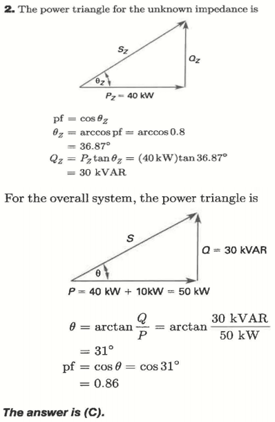
However, the correct answer is as shown below:

My question is where is my mistake?
So, I added the below as of my understanding is my reasoning accurate or not?
However, the correct answer is as shown below:

My question is where is my mistake?
So, I added the below as of my understanding is my reasoning accurate or not?
Your correctly found that the real power of the total circuit is the sum of the real powers of the components. However, you made a mistake by assuming you could just add the the apparent powers (Volt-amps).
$$S_t \ne S_1 + S_2$$
(at least not if S is a scalar (which it usually is, and definitely is in this case) rather than a vector)
You need to calculate the reactive powers of each component and add them. The reactive power of the resistance is of course 0. The reactive power of the unknown load is calculated in the answer. You need to find that, and you didn't. Once you know the total reactive power, and the total real power, you can find the total apparent power and/or the power factor.