0
\$\begingroup\$

I have a BLDC Y-shaped motor. I connected the Hall sensors and winding to a logic analyzer to see the combination of back EMF on thr windings. My intention is to eventually create a commutation table to spin the motor with sensors.

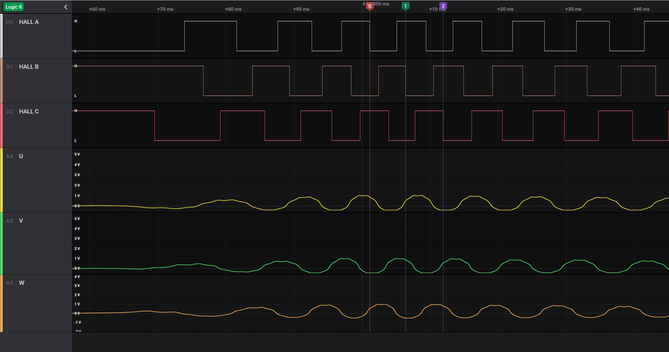
With the logic analyzer, I manually spin the motor in, for example, clockwise direction, and see the output on analyzer as the following:

Clockwise

So based on the back EMF and Hall sensor combination, let's say I decide to assign these three windings to be U, V, W as shown in the above picture

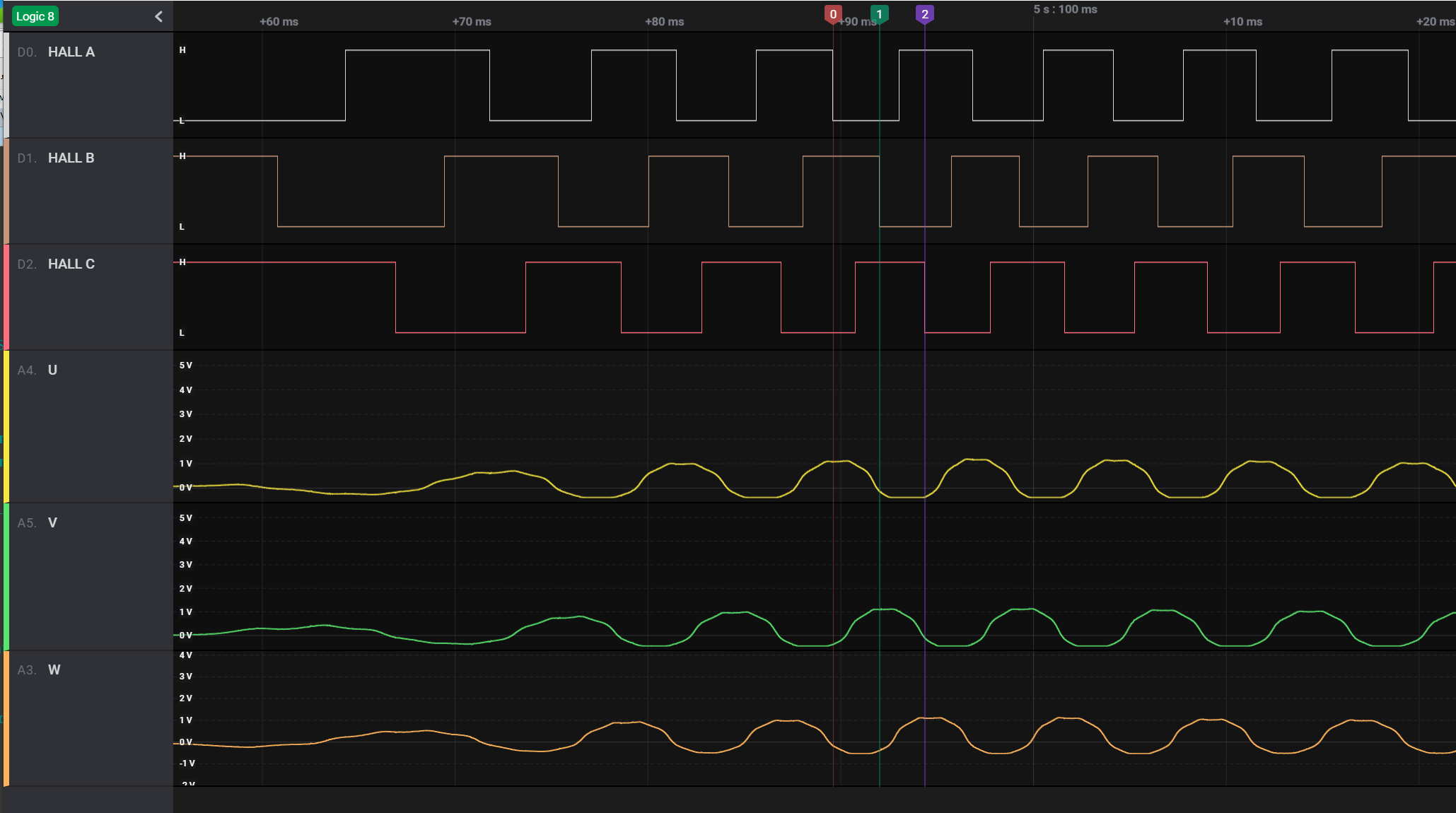
Then, I spin it in reverse direction, in this case counter-clockwise, and then I see the following:

Counter-clockwise

As shown, the combination does not match.

I was expecting to see when at the same state of Hall sensors (which means the positions are the same), both directions should cause the windings to have the same back EMF, either HIGH or LOW.

Did I misunderstand something? How can I see different combinations of windings<->Hall sensors just because of spinning in different direction?

\$\endgroup\$
1
  • \$\begingroup\$ That’s correct 2 Hall sensors and 2 drivers must be swapped to function properly in reverse. But only 1 combination works. \$\endgroup\$
    – D.A.S.
    Commented Jan 13, 2021 at 3:49

1 Answer 1

1
\$\begingroup\$

Before making an erroneous conclusion you have to understand how hall sensors for detecting a rotating PM field inside a BLDC works.

They change its state when pole changes, for example it turn to HI when passing N->S an they turn LO when passing S->N pole. If you spin the rotor backwards, then the same position at transition 1->0, now corresponds at transition 0->1 and the BEMF changes its sign due to negative rotation sign.

You can see that those signals you have marked at transition 1->0 correspond to +peak value on certain phase. Now observe the transition 0->1 of the same sensor, you'll see you get the -peak value of the same phase.

\$\endgroup\$
2
  • \$\begingroup\$ I understand that the same direction when hall sensor 1->0 correspond to +peak, 0->1 will match with the same phase of -peak. But shouldn't it has the same hall sensor and winding match when spinning the opposite direction? From the two pictures I've posted I cannot really tell that that is the case. \$\endgroup\$
    – jcy
    Commented Jan 26, 2021 at 14:57
  • \$\begingroup\$ @jcy "hall sensor 1->0 correspond to +peak, 0->1 will match with the same phase of -peak." I didn't said that. Rather, 1->0 correspond to +peak, if you spin backwards it changes to 0->1, but with -peak. You are evaluating just 1->0 transitions in both pictures, which doesn't make sense since the rotation is inverted. \$\endgroup\$ Commented Jan 26, 2021 at 16:36

Your Answer

By clicking “Post Your Answer”, you agree to our terms of service and acknowledge you have read our privacy policy.

Not the answer you're looking for? Browse other questions tagged or ask your own question.