0
\$\begingroup\$

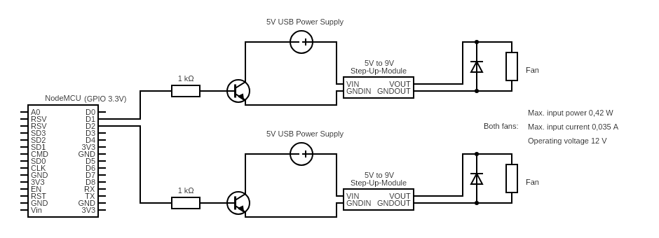
I'm working on my first circuit, controlling closet fans with an ESP32. I did some research drew the following circuit. I control the flow to GND from a 5V USB power supply with the GPIO pin thorugh the transistor. The fans would want 12V, but work with 5V just as well. I use the step-up-module to increase the airflow.

circuit

The 1k Ohm resistor should protect the base of the transistor (BC547B) and the diode is used as a " flyback diode", to protect the transistor as well. I've gathered that from this question. For this I bought a mix of common diodes (IN4001 4004 4007 5404 5406 5408 RL207 FR107 207 UF4007 IN5817 5819 5822 4148).

The question is, if the transistor is used safely in this circuit and what diode is best used here?

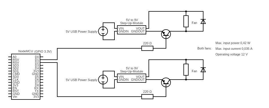
EDIT: I've updated the above shown circuit with feedback from the community:

EDIT 2: A second update of the circuit.

enter image description here

\$\endgroup\$
13
  • \$\begingroup\$ What is the model# of your step up module? The grounds are not quite right (or the NPN is reversed). Please label the grounds \$\endgroup\$
    – Voltage Spike
    Commented Jan 19, 2021 at 16:31
  • \$\begingroup\$ 1k is too high to switch onto a saturated NPN that may draw >100mA starting up , try 50 to 220 Ohms , any diode will do and is needed on the collector where it is switched. But it would be ok to switch the output load from the low side instead \$\endgroup\$
    – D.A.S.
    Commented Jan 19, 2021 at 16:31
  • \$\begingroup\$ The transistor looks like it is in the wrong place - I would expect to see it driving one side of the fan (both circuits). \$\endgroup\$ Commented Jan 19, 2021 at 16:32
  • \$\begingroup\$ @VoltageSpike I have a "MT3608 DC-DC Adapter Step-up module" \$\endgroup\$
    – emma.makes
    Commented Jan 19, 2021 at 16:32
  • \$\begingroup\$ @TonyStewartSunnyskyguyEE75 thank you, I'll reduce the ohm on the resistor and use one of the diodes from the pack, if it's placed correctly in my circuit. \$\endgroup\$
    – emma.makes
    Commented Jan 19, 2021 at 16:33

2 Answers 2

2
\$\begingroup\$

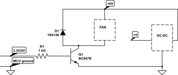
Your diagram lacks grounds but I can get the idea.

It would be better to switch the 9V with the transistors. The current will be lower and the step-up module may have some nasty characteristics (like a big input capacitor) that could cause problems when it switches on. The DC current switching the 5V might be in the 75mA range vs 35mA switching the fan directly.

The purpose of the resistor is not just to prevent the transistor from dying but to control the base current so that it saturates when on. The 1K may be a bit too high for that purpose. BC547B is okay with Ic/Ib = 20.

With 3.1V drive and 0.7 Vbe the base current is 2.4V/R. So for 75mA you'd want about 620 ohms and for 35mA 1K or 1.3K is okay.

As far as the diodes go, I am not sure they are actually necessary, even with the transistor switching the fan directly, but it costs little to add them. Any of the types mentioned are fine. I would use 1N4148s or 1N400x.

schematic

simulate this circuit – Schematic created using CircuitLab

The only disadvantage of leaving the DC-DC converter(s) running all the time is a bit more power consumption from the quiescent current the step-up converters draw, but it should not be much in comparison to the ~1W the fans draw in operation.

\$\endgroup\$
12
  • \$\begingroup\$ Hello and thank you very much for the elaborate answer! I have a lot to learn, this is my first circuit, I came up with. I've added your suggestions to the revised version of my circuit in the question! \$\endgroup\$
    – emma.makes
    Commented Jan 19, 2021 at 17:08
  • \$\begingroup\$ Ok, but don't forget the grounds or it won't work, and could even cause damage. \$\endgroup\$ Commented Jan 19, 2021 at 17:26
  • \$\begingroup\$ This is exactly what I said \$\endgroup\$
    – D.A.S.
    Commented Jan 19, 2021 at 18:04
  • \$\begingroup\$ Illuminati confirmed. \$\endgroup\$ Commented Jan 19, 2021 at 18:05
  • \$\begingroup\$ Except I explained the reasons for the diode. Hey are you busy with any projects? \$\endgroup\$
    – D.A.S.
    Commented Jan 19, 2021 at 18:07
0
\$\begingroup\$

The purpose of the diode is quench the stored energy in an switched off inductive load.

Your transistor is the switch so it needs the diode, ... which could in practice will switch the output better than the input to the boost converter. Presuming that the no load current is ok when the fan is off and boostconverter still running.

  • it is wise to move the switch to the output and switch the fan -ve with the diode you have placed there. The fan load appears like a damped resistive load with a capacitance in parallel as it commutates at some freq. due to internal caps. (.i.e. the current rises linearly with voltage)
  • yet accelerating the voltage changes will draw more current until steady state.
  • The boost converter will have more surge current than the fan . This is why it is better to switch the output and easier on the low side of the load.
\$\endgroup\$
3
  • \$\begingroup\$ Hello Tony - thank you very much for your help! I'm very new to all of this and tried to understand. I've updated the circuit in the original question. Would you have a look? I hope I didn't mess up your advice too much. \$\endgroup\$
    – emma.makes
    Commented Jan 19, 2021 at 16:52
  • \$\begingroup\$ @emma.makes - disconnect the GNDOUT from the transistors; connect GNDOUT to GNDIN (this will be your common ground), Connect the transistor emitter to ground and the collector to the low side of the fan, \$\endgroup\$ Commented Jan 19, 2021 at 16:56
  • \$\begingroup\$ @PeterSmith Thank you for the feedback! I've revised the circuit in the question \$\endgroup\$
    – emma.makes
    Commented Jan 19, 2021 at 17:07

Your Answer

By clicking “Post Your Answer”, you agree to our terms of service and acknowledge you have read our privacy policy.

Not the answer you're looking for? Browse other questions tagged or ask your own question.