0
\$\begingroup\$

I have 3 D cell alkaline batteries in series. They are rated at 20Ah. https://uk.rs-online.com/web/p/d-batteries/9145058/

The circuit spend most of its time in deep sleep only consuming 8 uA of current. Whilst active, it has the following current demands:

  1. Between 40mA to 60mA for RF module.
  2. Roughly 50mA for the MCU and other sensors.
  3. Between 300mA to possibly upto 1A for servo, which only drives the load from 0-180 for 10 times during 24h.

In case you guys wondering why use such heavy duty batteries, the aim of the product is to last 3 -5 years on batteries.

In my design what I have done so far is, I have used a 250mA LDO to power the MCU and other circuit whilst I supplied the servo power directly from the battery, whilst servo PWM control is coming from the MCU. https://uk.rs-online.com/web/p/low-dropout-voltage-regulators/6694897/

My servo circuit is shown. I have 100uF to account for peak current surges. My servo is SG90 https://www.rapidonline.com/rvfm-tower-pro-sg90-mini-servo-37-1330.

Now my circuit works fine for most of the time, but sometimes servo fails to operate the load. I have a couple of choices here.

  1. I could increase the capacitor from 100uF to possibly 1F cap.
  2. Use a boost for the voltage supply for the servo because I am mindful the 3 x 1.5V alkaline batteries in series are 4.5V. Boosting the servo voltage to 6V might be good way forward.

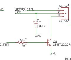
enter image description here

\$\endgroup\$
3
  • \$\begingroup\$ How much current does the servo pull, and is the 2N2222 able to handle such current without too much voltage drop? Also, the circuit is switching the servo GND while leaving the VCC, so depending on the servo PWM pin interface, it may try to power up via the PWM pin. Which state you leave the PWM pin when the motor is unpowered, high, low, PWM, high-z? What is the PWM signal voltage, 3.3V? \$\endgroup\$
    – Justme
    Commented Feb 1, 2021 at 8:37
  • \$\begingroup\$ Usually servo pulls upto 300mA to 500mA but sometimes It could pull more current. The 2N2222 have max DC current of .6A, its part number is MMBT2222A-7-F. PWM is left in low state and signal voltage is 3.3v. \$\endgroup\$
    – AD Friend
    Commented Feb 1, 2021 at 8:47
  • \$\begingroup\$ "the aim of the product is to last 3 -5 years on batteries." - Why? \$\endgroup\$ Commented Feb 1, 2021 at 11:05

2 Answers 2

1
\$\begingroup\$

Now my circuit works fine for most of the time, but sometimes servo fails to operate the load.

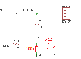
You try the simplest things first and that means changing the servo drive from a feeble MMBT2222 to an n channel MOSFET with low on resistance: -

enter image description here

If that fails to work correctly then you use a boost converter to produce a higher voltage.

I could increase the cap from 100uF to possibly 1F cap

Unless you have a particular problem that is seen at (for example) low temperatures where battery drive strength may be impaired, this doesn't sound like a good idea. Do the MOSFET thing first.

\$\endgroup\$
7
  • \$\begingroup\$ Its good suggestion going forward, I will replace npn with NMos, to find solution for PCBs already manufactured, It could de-solder the NPN and short the pin to ground, which might result in more power lost, or I could find NMOS which has pins Drain source and gate arrange according to my NPN footprint \$\endgroup\$
    – AD Friend
    Commented Feb 1, 2021 at 11:59
  • \$\begingroup\$ @ADFriend when you pick one, let me know which it is and I'll double check stuff but you need to mention what input level you have to the 510 ohm resistor. \$\endgroup\$
    – Andy aka
    Commented Feb 1, 2021 at 13:11
  • \$\begingroup\$ 3.3V input from Atmega328p is fed into 510 ohm \$\endgroup\$
    – AD Friend
    Commented Feb 1, 2021 at 13:41
  • \$\begingroup\$ OK you need to find a MOSFET that has a Vgs threshold of probably around 1 volt to 1.5 volts. \$\endgroup\$
    – Andy aka
    Commented Feb 1, 2021 at 13:42
  • \$\begingroup\$ diodes.com/assets/Datasheets/ds30929.pdf I think this one should be fine.. Do I need 100K resistor to GND, since my old PCBs won't have space or footprint on the board for this ? \$\endgroup\$
    – AD Friend
    Commented Feb 1, 2021 at 15:37
0
\$\begingroup\$

Is gearing your servo an option? That could drop the static load and corresponding power requirement enough to avoid having to change the electronics, provided that you aren’t depending on servo speed for your application.

\$\endgroup\$
3
  • \$\begingroup\$ I believe servo is already geared. \$\endgroup\$
    – AD Friend
    Commented Feb 1, 2021 at 8:36
  • \$\begingroup\$ Yes but can you gear it down more? \$\endgroup\$
    – pion
    Commented Feb 1, 2021 at 8:38
  • \$\begingroup\$ Yes I can try to gear it down further, but its not ideal, due to mechanical assembly of the product. But the application is not depending on the servo speed. \$\endgroup\$
    – AD Friend
    Commented Feb 1, 2021 at 8:48

Your Answer

By clicking “Post Your Answer”, you agree to our terms of service and acknowledge you have read our privacy policy.

Not the answer you're looking for? Browse other questions tagged or ask your own question.