0
\$\begingroup\$

I am interested in Linux device drivers development and needed a cheap and tiny USB supporting device that I could control, so that I could write software for both the gadget and the host.

I decided to use the ATmega328P AVR microcontroller, for which there is a USB supporting library - V-USB.

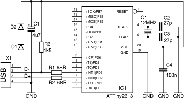
However, I cannot connect USB to it as it requires some electronic skills. Connecting the components in the circuit is rather simple, I just have a problem identifying them. Here is the diagram:

enter image description here

  • What is the difference between C1 and C2, C3, C4 capacitors?
  • What diodes should I use as D1 and D2? Description says "D1 and D2 are a low cost replacement for a low drop 3.3 V regulator chip, such as the LE33," but it doesn't mention their parameters.
  • Which oscillator should I use? I understand it must be a 12 MHz oscillator but it must also have 1 coulomb charge?
\$\endgroup\$
5
  • 3
    \$\begingroup\$ The difference between C1/C2 and C4 is the value. C3 is electrolytic unlike the others. The diodes are regular diodes with standard 0.7V Vf, so they can "eat up" the extra voltage from the power supply. Q1 is a designator of the oscillator and has nothing to do with charges. \$\endgroup\$
    – Eugene Sh.
    Commented Feb 19, 2021 at 14:51
  • \$\begingroup\$ If you want to use an ATmega328P, why are you asking questions about a circuit with an ATTiny2313? They are not even close to the same thing. \$\endgroup\$
    – spuck
    Commented Feb 19, 2021 at 15:31
  • \$\begingroup\$ V-USB works on both of them. \$\endgroup\$
    – yomol777
    Commented Feb 19, 2021 at 15:33
  • \$\begingroup\$ @yomol777 It might, but the ATMega328P cannot run at 12 MHz unless the voltage is at least 3.6V. Overclocking it means some chips might work, but it may simply not work or it might be glitcy when it is run outside the conditions it is meant to run. \$\endgroup\$
    – Justme
    Commented Feb 19, 2021 at 16:49
  • \$\begingroup\$ OK. Still, I can use zener diodes to reduce output voltage to 3.3V. \$\endgroup\$
    – yomol777
    Commented Feb 19, 2021 at 18:41

2 Answers 2

2
\$\begingroup\$

Cx is a typical designator for a capacitor.

  • C1 is a polarized electrolytic capacitor (notice the little + and the empty rectangle at the top) and has a value of 4u7 which stands for 4.7 µF
  • C2 and C3 are very small capacitors (22 pF) used as loading capacitors for the quartz crystal, these should be ceramic capacitors, preferably using a NP0 dielectric material
  • C4 is a typical 100 nF power supply bypass capacitor, use a ceramic one as well, but it doesn't need to be NP0. This should be close to the chip.

Dx is a designator for diodes (all kind of diodes)

If D1 and D2 are low cost replacements for a 3.3 V regulator, use normal silicon diodes which can handle enough current for the device, probably something with 100 mA would be fine, so 1N4001 or something would be fine.


Q is a designator used for different stuff, for one it can be a crystal or resonator, but it is also commonly used for transistors. It does not denote charge.

12 MHz should probably work with a lot of types. You might want to check the datasheet of the controller if they recommend a certain type.

Layout is critical for the clock, try to get the crystal as close as possible to the chip and the capacitors as well. If the leads are too long parasitic effects might prevent it from oscillating.

Also note that the crystal usually defines the value of the capacitors, so check the datasheet of the crystal for the size of the loading capacitors, they might be just 9 pF for a certain type.

A lot will just work even if you don't put much care into it, but not reliably so.

\$\endgroup\$
2
  • \$\begingroup\$ Thanks. That helped me a lot. I want to build this circuit on the breadboard (no soldering). If oscillators have such high requirements, will this even work? Some circuits do not work on such boards (eg radio circuits). \$\endgroup\$
    – yomol777
    Commented Feb 19, 2021 at 15:06
  • \$\begingroup\$ I don't have many experiences with breadboards. I have doubts that it will work correctly with 12 MHz (and it will probably be a nightmare to figure out what is going wrong where). So the advice from @Justme to use a ready made board with a controller equipped to handle USB would make your life easier I think. \$\endgroup\$
    – Arsenal
    Commented Feb 19, 2021 at 15:11
4
\$\begingroup\$
  1. Different capacitors are for different purposes, and thus are of different types and different capacitances. C1 and C4 are for power supply filtering. C2 and C3 are load capacitors to the crystal to make it vibrate at the right frequency.

  2. D1 and D2 are diodes. We don't know any more about them than you do. Most likely almost any standard small signal would do, but I will not suggest any type so I am not responsible if it damages your computer.

  3. That is not an oscillator. That is simply a 12 MHz crystal. It does not have 1 coulomb charge, crystals are labeled Q and thus first crystal is Q1. The other parameters are unknown. Based on the 27pF capacitors, this crystal must have load capacitance rating of at least 13.5pF, perhaps 16pF to 20pF.

Beware that this circuit is rather tricky and the AVR actually has no hardware support for USB. If you must build it yourself, beware that any mistake can damage your USB port or whole computer permanently. I would not use thiäe above circuit myself or recommend it for any purpose. Better spend the approximately $20 amount of money on something that is a ready built board with much more capable MCU with hardware USB support, such as many of the STM32 Nucleo boards.

\$\endgroup\$
3
  • \$\begingroup\$ Good point about the downsides of the circuit. \$\endgroup\$
    – Arsenal
    Commented Feb 19, 2021 at 15:00
  • \$\begingroup\$ But as long as I'm using USB to power it, it's safe because I can't generate a higher voltage than what comes from it, somehow. \$\endgroup\$
    – yomol777
    Commented Feb 19, 2021 at 15:14
  • \$\begingroup\$ No, not higher, but if you accidentally connect the 5V to one of the USB data pins, nobody can guarantee if the PC survives it. The diodes are also very bad replacement for a real 3.3V regulator, as it depends on the load current how much the diodes will drop. And depending on which exact Tiny2313 model you get, may or may not be rated to run at 12 MHz with 3.3V supply. How are you going to upload the firmware into the AVR? \$\endgroup\$
    – Justme
    Commented Feb 19, 2021 at 15:56

Your Answer

By clicking “Post Your Answer”, you agree to our terms of service and acknowledge you have read our privacy policy.

Not the answer you're looking for? Browse other questions tagged or ask your own question.