0
\$\begingroup\$

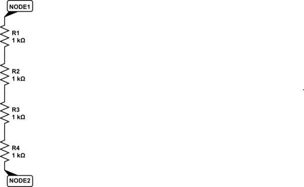
I have a chain of 4 single resistors in series. Call them R1, R2, R3, R4. When I measure the total resistance from top to bottom, then I get the same result as if I measure each pair of resistors: (R1+R2) + (R3+R4). I usually get the same result if I measure the resistors this way: R1 + (R2+R3) + R4.

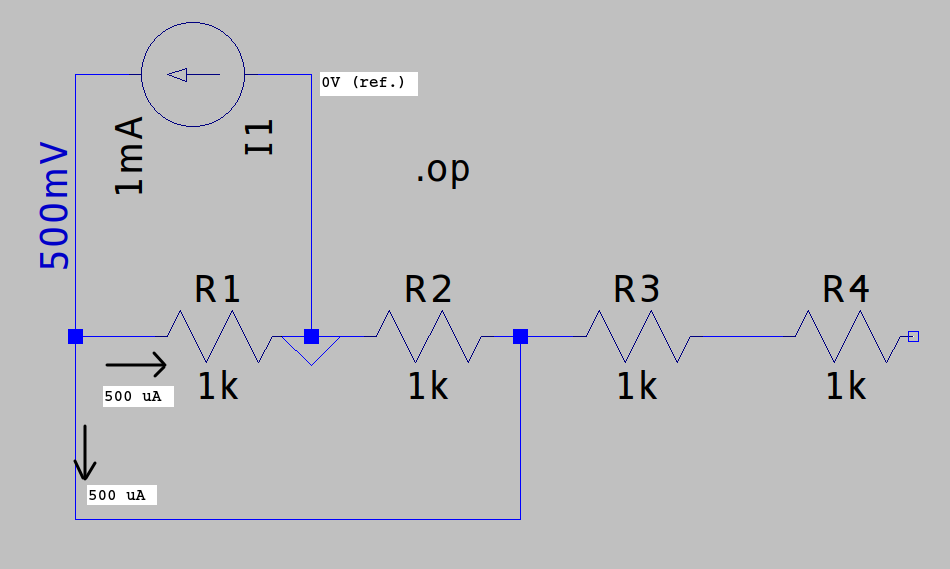
I say "usually" because if I now install a jumper between the top of R1 and the bottom of R2, then the results are not the same. Measuring R1 now gives the value equal to R1 in parallel with R2, making the sum of the measurements equal to more than the total resistance measured from top to bottom.

If for example each resistor is 1 kohm, then the total resistance with R1 and R2 jumpered is 2 kohm. But if I measure R1 + (R2+R3) + R4, then the total is 3 kOhm.

This is based on a real-life situation where we can only easily measure the junction between resistors R1 and R2, the junction between R3 and R4, etc. And we can't measure the total resistance at once, because it is thousands of megohms. Is there some way to mathematically extract the correct total resistance from this type of measurement?

\$\endgroup\$
5
  • 1
    \$\begingroup\$ You have the correct resistance. The jumper around R1 and R2 puts the two resistors in parallel. \$\endgroup\$
    – JRE
    Commented Feb 25, 2021 at 10:27
  • 7
    \$\begingroup\$ There is no paradox. \$\endgroup\$
    – Andy aka
    Commented Feb 25, 2021 at 10:28
  • \$\begingroup\$ Probably, but you are asking a maths question \$\endgroup\$ Commented Feb 25, 2021 at 10:32
  • \$\begingroup\$ You just can't measure a resistor resistance with an ohm-meter when there is more than one path from one end of a resistor to another. And you do have another path - via R2 and the jumper. You measure combined resistance of the two parallel paths. \$\endgroup\$
    – AlexVB
    Commented Feb 25, 2021 at 10:48
  • \$\begingroup\$ I understand the value of two resistors in parallel. I'm looking for a way to get around the real-life measurement limitations. \$\endgroup\$
    – theber
    Commented Feb 25, 2021 at 11:05

2 Answers 2

6
\$\begingroup\$

There's no paradox, just a misunderstanding of the circuit - and the fact that you are measuring different circuits.

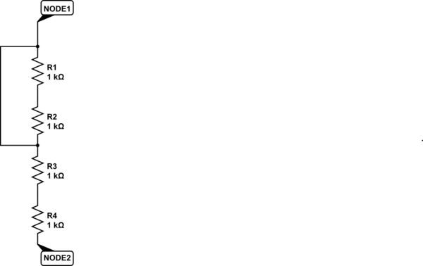
Here's your original circuit, 4 resistors in series:

schematic

simulate this circuit – Schematic created using CircuitLab

The total resistance is 4*1k = 4000 ohms.

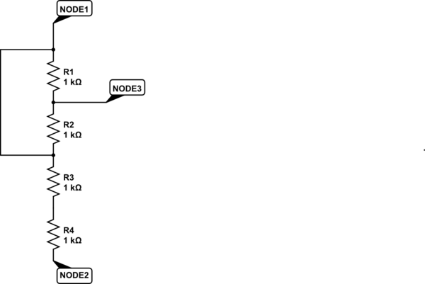
Now here's your circuit with the jumper between "the top of R1 and the bottom of R2.":

schematic

simulate this circuit

R1 and R2 are shorted - if you measure from Node1 to Node2, the total resistance will be only 2k.

In your next case, you have chosen a new node to measure from:

schematic

simulate this circuit

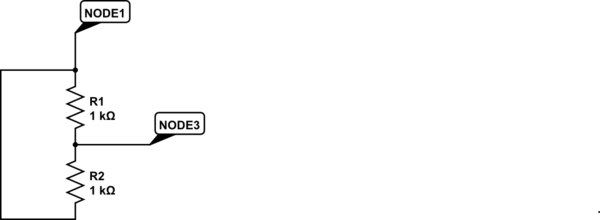
You are now measuring between Node1 and Node3. Resistors R3 and R4 are no longer connected to the ohmmeter and have no effect on the resistance measured between Node1 and Node3.

The circuit is effectively just this:

schematic

simulate this circuit

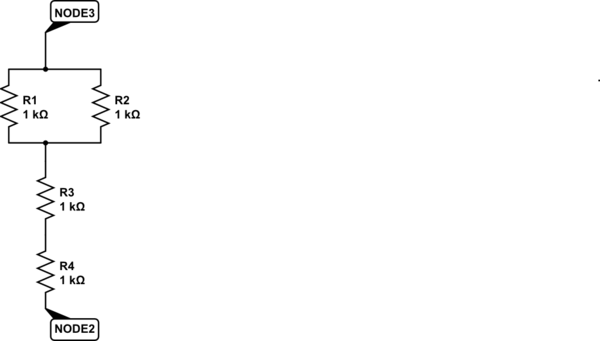
That can be redrawn to this simple looking (but electrically identical) circuit:

schematic

simulate this circuit

Finally, you get to the effect of measuring from the junction of R1 and R2 (Node3) with the other ends of R1 and R2 shorted:

schematic

simulate this circuit

Looked at like that, you are measuring the resistance of different circuits. Each circuit can have a different resistance, and it's no paradox that the same parts with different connections can have a different total resistance as seen from different junctions.


The problem with measuring the resistance of parts in a circuit (on a printed circuit board, for example) is that you don't know what else is connected where. You can't mathematically account for things if you don't know what they are and how they are connected.

\$\endgroup\$
1
  • \$\begingroup\$ That does answer my question, thanks. \$\endgroup\$
    – theber
    Commented Feb 25, 2021 at 11:13
0
\$\begingroup\$

To measure resistance your meter determines the result from known voltage and current values.

By "jumping" the resistors, as you mentioned, the two other resistors are not in the "measurement circuit". The two you are measuring divide the test current, hence you measure their parallel equivalent.

enter image description here

\$\endgroup\$

Your Answer

By clicking “Post Your Answer”, you agree to our terms of service and acknowledge you have read our privacy policy.

Not the answer you're looking for? Browse other questions tagged or ask your own question.