0
\$\begingroup\$

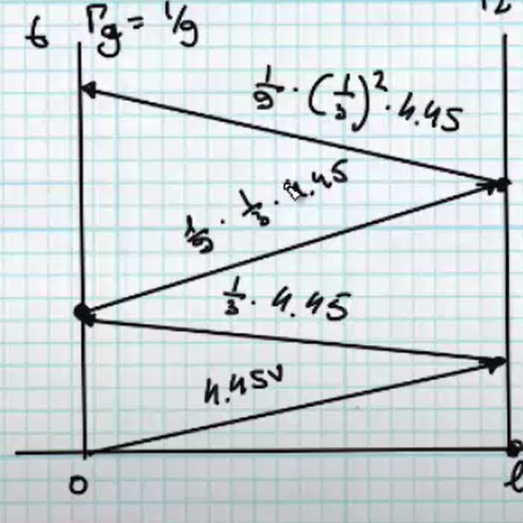
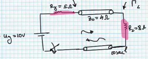
Based on the circuit below I have built the voltage based TDR diagram.

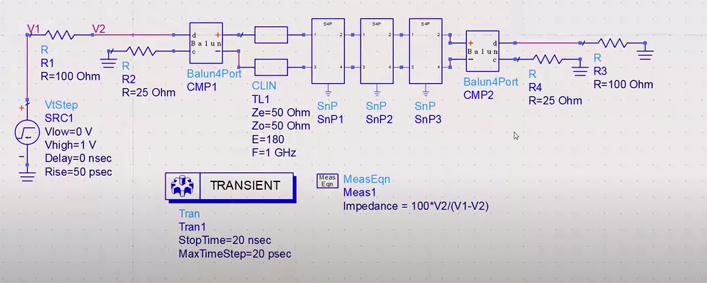
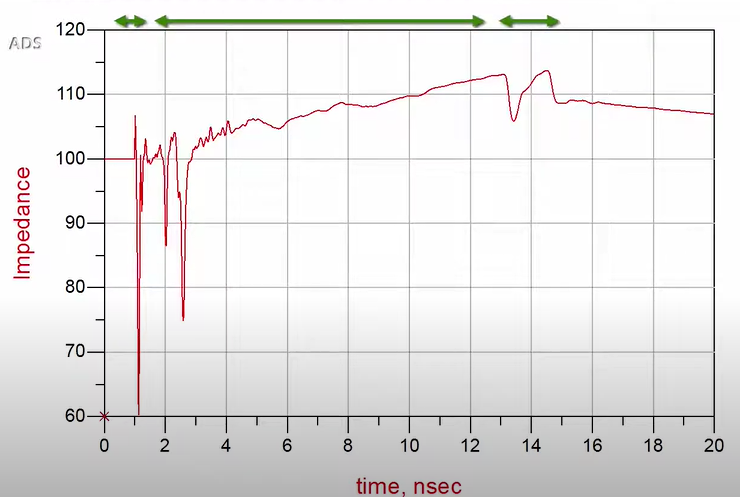
Then I went to the ADS TDR simulation and constructed by the manual the circuit below.

In the ADS circuit they say that IMPEDANCE=V/I=V/(delta(V)/R)=V*R/Voltage_drop_over_R

I can't see the logic of this formula.

Why does measuring impedance on the left side of the transmission line over time means its the impedance at some location in the transmission line?

enter image description here

enter image description here

enter image description here

enter image description here

\$\endgroup\$
4
  • \$\begingroup\$ Try using mathjax i.e. \$Z = \dfrac{V}{\frac{\delta V}{R}}\$ = \$Z = \dfrac{V}{\frac{\delta V}{R}}\$ \$\endgroup\$
    – Andy aka
    Commented Mar 11, 2021 at 12:50
  • \$\begingroup\$ I fully appreciate how some people pronounce english words differently and my spelling is often poor, yet I recommend Grammarly for anyone. \$\endgroup\$
    – D.A.S.
    Commented Mar 11, 2021 at 12:50
  • \$\begingroup\$ None of the symbols in your formula appear in either schematic, so I don’t know what they refer to. However, if V is the voltage drop across a 2-terminal component A in any branch, R is a resistor in the same branch, and I is (voltage drop across R)/R, then it is certainly true that V/I is the impedance at A (the voltage across A divided by the current through A). This does not tell us the impedance anywhere else in the circuit. \$\endgroup\$
    – 10ppb
    Commented Mar 11, 2021 at 13:50
  • \$\begingroup\$ Hello 10ppb,I have implemented an official keysight manual shown bellow. they say its impedance at every point(time varying location) youtube.com/watch?v=U3be5KkGmAc&t=121s \$\endgroup\$
    – ron398
    Commented Mar 11, 2021 at 14:31

1 Answer 1

-1
\$\begingroup\$

For dynamic signals such as Solar Panels and microwave, we sometimes find Ohm's law is useful for incremental resistance as well as the max power theorem and for the mean impedance.

\$Z(t)=\dfrac{V(t)}{I(t)} = \dfrac{δV(t)}{δI(t)}\$

Similarily yet different for a Solar Panel's MPPT operating point. \$Z_{mpt}=\dfrac{δV(t)}{δI(t)}\$ where V*I is max and \$Z_{mpt}\dfrac{V_{mpt}}{I_{mpt}}= \dfrac{V_{oc}}{I_{sc}}\$

Another distant relative of this is Load Regulation, where if we know a power supply as 1% load regulation voltage error at some load R , we can imply that the source impedance must be 1% of R.

\$\endgroup\$

Your Answer

By clicking “Post Your Answer”, you agree to our terms of service and acknowledge you have read our privacy policy.

Not the answer you're looking for? Browse other questions tagged or ask your own question.