0
\$\begingroup\$

Can someone please just sanity check my math?

I'm trying to design two voltage divider networks, one for the solar panel and one for a LiPo battery so that I can connect them to my 3.3V ADC (RP2040)

RP2040 Datasheet: https://datasheets.raspberrypi.org/rp2040/rp2040-datasheet.pdf

Page 579 has some info on the ADC.

Someone else also performed their own ADC Tests: https://pico-adc.markomo.me/

I've tried to pick as large a resistance as I have in my box of parts to minimise current drain, which I believe is the correct thing to do.

The 12V solar panel open circuit voltage is ~20V. Although it will never be open, I'm designing to allow for overhead just in case.

$$ Vout = \frac{(25V)(68,000 Ω)}{68,000 Ω + 470,000 Ω} = 3.16V \because V_{\text{out}} = \frac{V_{\text{in}}(R_2)}{(R_1 + R_2)} $$

$$ I =\frac{25V}{68,000 Ω + 220,000 Ω} = 0.0000465A \because I = \frac{U}{R} $$

The same for my LiPo battery, where the maximum voltage will be 4.7V

$$ V_{\text{out}} = \frac{(4.7\text{ V})(470,000 Ω)}{220,000 Ω + 470,000 Ω} = 3.2\text{ V} $$

$$ I =\frac{4.7\text{ V}}{220,000 Ω + 470,000 Ω} = 0.00000681\text{ A} $$

If I've done my math right, there should be 0.00116 Watts and 0.000032 Watts dissipated respectively.

Do you think I'll have any problems with these? Are they safe? Are there better values to pick?

\$\endgroup\$
7
  • \$\begingroup\$ The larger the resistance you use in this divider, the larger the Johnson-Nyquist noise. Can your ADC and code deal with that? \$\endgroup\$
    – Hearth
    Commented Mar 22, 2021 at 15:25
  • \$\begingroup\$ The 12-bit ADC in question has 9.3 Bits of Noise-free resolution and can perform 1 second averages (with 500kS/s), I don't need it be massively accurate, but resolution to 2dp should easily be possible. \$\endgroup\$ Commented Mar 22, 2021 at 15:44
  • \$\begingroup\$ Please provide a link to the manufacturer's datasheet for the ADC and/or RP2040. We really need to see that. \$\endgroup\$ Commented Mar 22, 2021 at 15:44
  • 1
    \$\begingroup\$ At a wild guess, 2 decimal places. \$\endgroup\$
    – user16324
    Commented Mar 22, 2021 at 15:45
  • 1
    \$\begingroup\$ @BrianDrummond As a native English speaker that was also my assumption, but not all of the readers here would get that. Also, "2 decimal places" doesn't really tell the whole story...is the maximum value 99.99 or is it 0.99? \$\endgroup\$ Commented Mar 22, 2021 at 16:29

1 Answer 1

1
\$\begingroup\$

I ran your resistor values and voltages through this voltage divider calculator. It comes up with different values than you got.

For 25V, 220K and 68k, it says the output voltage will be 5.9V compared to your 3.16V.

For 4.7V,220k and 440k, it says the output voltage will be 3.13V compared to your 3.2V (probably differences in rounding.)

Incorrect version (I had the resistors reversed): For 4.7V, 440k and 220k, it says the output voltage will be 1.5V compared to your 3.2V.

Besides whatever problem there are with the calculated values, you've made your calculations without regard to the impedance of the ADCs.

In the RP2040 datasheet, you will find this notice on page 581:

The ADC input is capacitive, and when sampling, it places about 1pF across the input (there will be additionalcapacitance from outside the ADC, such as packaging and PCB routing, to add to this). The effective impedance, even when sampling at 500kS/s, is over 100kΩ, and for dc measurements there should be no need to buffer.

There'd be no need to buffer normal, low impedance signals.

Your voltage dividers are at or above the impedance of the ADC input, however.

You need to either use smaller resistors to keep the impedance of the voltage dividers much lower than the input impedance of the ADC, or you need to use a buffer amplifier between the voltage divider and the ADC.

If the RP2040 has selectable conversion time, then you could probably get away with the high value resistors - a very long conversion time effectively raises the input impedance.


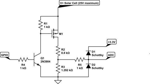
You could switch the voltage divider on and off when measuring voltage like this:

schematic

simulate this circuit – Schematic created using CircuitLab

A high on the GPIO turns on the voltage divider, a low turns it off. When off, you only have the (very low) leakage current through the MOSFET instead of the full current through the low impedance voltage divider.

\$\endgroup\$
1
  • \$\begingroup\$ I've updated my original question, I put the wrong version of my calculation, I've fixed it to R1 470K / R2 68K for the 25V divider \$\endgroup\$ Commented Mar 22, 2021 at 16:28

Your Answer

By clicking “Post Your Answer”, you agree to our terms of service and acknowledge you have read our privacy policy.

Not the answer you're looking for? Browse other questions tagged or ask your own question.