I've got a 24VDC logic board that controls 120VAC motors, we interact with the logic board via three-button remotes, and now I'm looking to add remote control and monitoring over our existing network.
Question (The short version):
I'm looking for a way to monitor a 13-24VDC line for changes in frequency (drop-out pulses at <5, 10, or >13 Hz) as well as voltage changes (I need 0.1V resolution across a range of 2.5V). I'll be using a 3.3V MCU that does not have an embedded ADC. I need to monitor for these changes while having as little effect on the circuit as possible (goal of no more than 3V drop and 30mA draw). A voltage divider using resistors would be simple but I'm struggling with the variable input and potential impacts across the circuit.
Thanks for any and all suggestions.
The long and rambling version is below.
Additional Background:
I've tested a simple circuit that basically replaces the momentary switches with NPN transistors and it works well.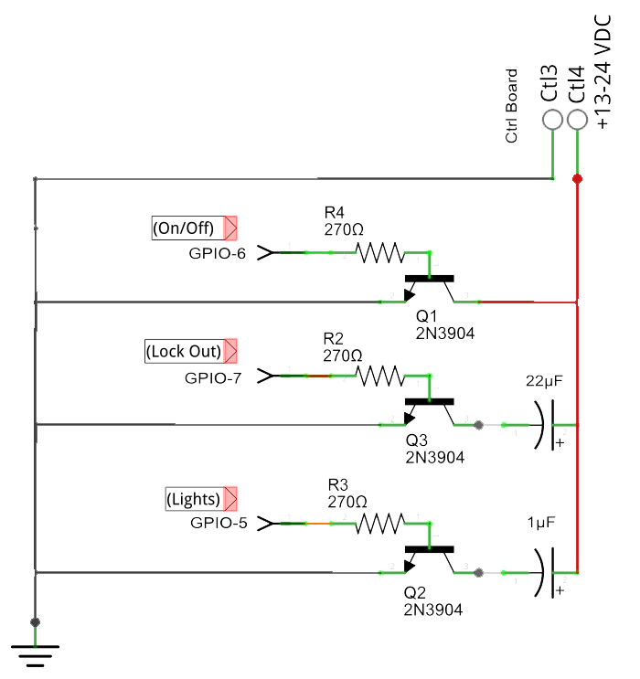
The challenge I'm having is with respect to remote monitoring.
While no decision has been made yet on the microcontroller that will be used, I'm working with the assumption that all GPIO pins will be 3.3v and there is no embedded ADC (yes, I realize most include this but I'd rather assume I'll need to supply an external ADC and a Vref from the board).
I've got 4 wires coming from the control board:
Ctl1 and Ctl2: These are +4.9VDC leads for two limit switches that share a common ground. When the switch is triggered it gets pulled to ground. I haven't tested this yet but my plan is to use a Zener to knock them both down to 3.3V and feed that directly to the MCU where I'll monitor state changes 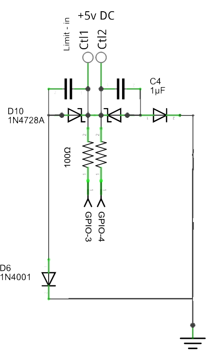 .
.
Ctl3 - This is the ground wire from the 24VDC control board Ctl4 - This is the V+ wire from the control board
Ctl4 will supply anywhere between 13.5V and 24V (Vmax) with all motors at rest and all peripherals off. Typically, this should be 17V but "stuff happens" and I need to account for the full range. This line gets pulled to ground two to four times per second during normal operations and there's ripple. 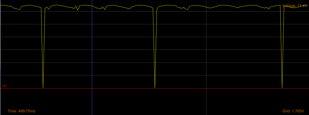
In case it isn't obvious yet, electronics aren't my thing. I've spent days reading about voltage dividers, ADCs, Op-Amps, etc and I'm still struggling to find the 'best' solution to the following:
Everything we need to monitor (aside from the limit switches) shows up in that V+ line in one of two ways: 1. Frequency of those drop-outs (I'm sure that's not the proper terminology but I'm simply referring to when Ctl4 gets pulled to ground back at the control board)
a) 1-5Hz tells us everything is 'normal' (as in the pic above)
b) 10-12Hz Rectangular - tells us the electronic lock-out has been engaged. If the lock-out is engaged it will be active for one minute at a minimum.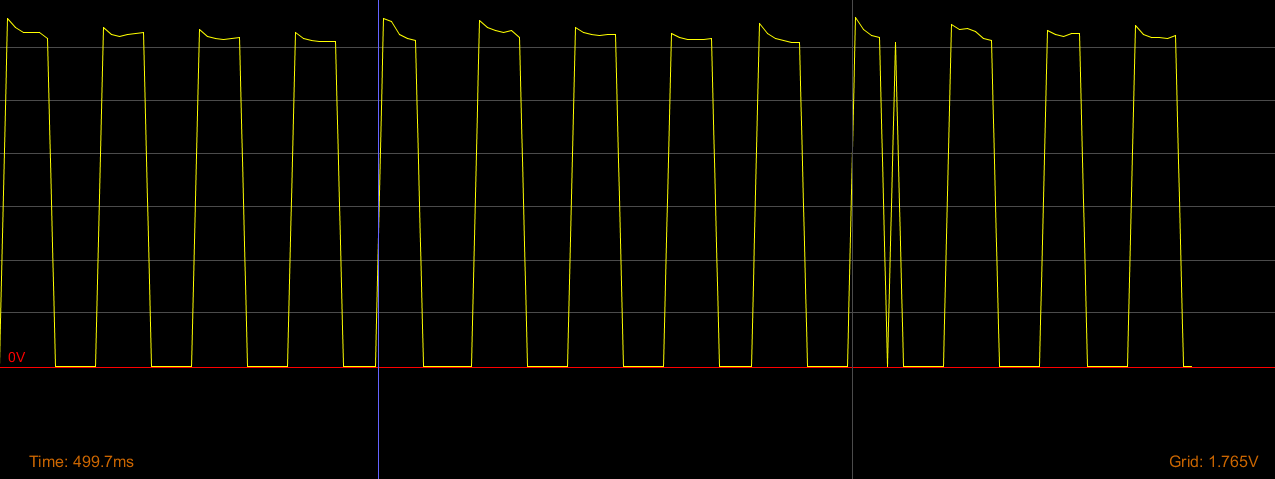
c) >12Hz - button presses and other events can result in rapid cycling. These are unlikely to last more than 2 seconds at a time and anything longer than 4 seconds indicates a problem.
My plan for this is to simply reduce the voltage to a maximum of 3.3V and handle frequency counting in the MCU.
Voltage changes in Ctl4 tell us everything else we need to know and this is the piece I'm stuck on. It seemed easy enough at first - I only need to have resolution to 0.1V for a range that won't exceed 2.5V (Vmax to Vmax-2.5). Here's where I'm at with all the above pieces together: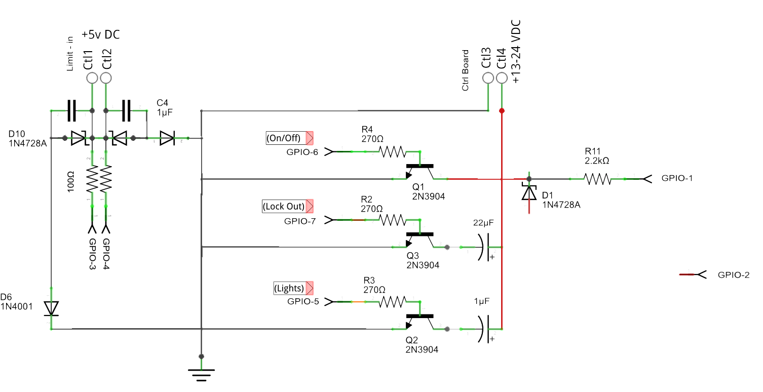
On the right is D1, a Zener to supply a steady 3.3V to the MCU so it can monitor frequency changes. This leaves me with a potential voltage of 10.2-20.7V that I was going to monitor for changes. I only care about the 'upper' 2.5V and at 8bits I believe I have plenty of resolution for what's left once I account for noise, etc. My operational concerns are that I need to have as little effect on the control lines as possible - a normal remote draws less than 30mA, it's unknown how much voltage loss would be acceptable (there's no easy way to test this but I know 3V would be OK), and if the circuit interferes with the Lock-out provision... well, that wouldn't be good. If I throw a voltage divider in under D1, am I likely to violate any of those operational concerns? Has that ship already sailed? Worst case scenario a piece of equipment fails but there's no risk to life or limb even if this all blows up ($500 fix and I look like a moron). I looked at the differential/inverting amplifiers but I understand their potential impacts even less.
If you'd care to offer a suggestion for an ADC (I'm ASSuming that's how I'll be monitoring for the voltage changes, via GPIO2), other suggestions/warnings or recommended readings, it's all appreciated. If you just want to tell me off for wasting your time with this novel, I understand.
I'd like to get this done with as few components as possible (e.g.: a $5 part would be preferable to 5 $0.10 components), in as small a space as possible while accounting for a worst-case scenario of 0-24V coming in on any of the Ctl lines.
Thanks in advance,
Brad
