0
\$\begingroup\$

The Leningrad is a computer from the Soviet Union which needs around 3.5 MHz clock pulse for the CPU, which is a Z80. It uses a 14MHz crystal. Below is the bit that shows how the Leningrad derives 3.5MHz from 14MHz.

We've got these three inverters in a 7404. As everyone knows, the identity function is identical to "not not", so not "not not" is not. That means that what's labelled 5 on here is the same as what's labelled 1.

Then that signal goes through a flip flop, and the output from that goes into another flip flop. I understand that these are each dividing the clock frequency by two, so that together with the 14MHz crystal, the circuit yields the /RAS at 3.5 MHz, the inverse of that, and a few other timing related bits and bobs.

But this is making me feel quizzical because

  1. The first inverter has its input and output pulled together by a 360Ω resistor. Why would you want to do that? Another copy of this schematic shows a 420Ω resistor in this place, so it looks like the value doesn't matter.
  2. The output from the first inverter is inverted another two times.
  3. I assume the crystal is somehow influencing the output of the second inverter, but my brain is too smooth to figure out how that's possible. From what I understand a crystal is normally connected to a voltage rail, but I don't see that here.
  • What's going on here?
  • Why does the signal need to be inverted so many times?
  • Why is the crystal causing the "not not" to sometimes not be "not not"?

I'm going to be building this circuit soon. Just to check I really get a clean clock pulse before hanging a Z80 and everything else off it.

Part of circuit for the Leningrad

\$\endgroup\$
3
  • 1
    \$\begingroup\$ The leftmost part is a crystal oscillator circuit. Crystals don't oscillate spontaneously: you need a circuit to drive them, and this is what the two inverters do. See en.wikipedia.org/wiki/… \$\endgroup\$
    – FrancoVS
    Commented Apr 14, 2021 at 13:07
  • \$\begingroup\$ To get this kind of oscillator going reliably, you may have to change the value of that 360 ohm resistor...crystal construction has changed over decades and their electrical characteristics have changed too. \$\endgroup\$
    – glen_geek
    Commented Apr 14, 2021 at 13:31
  • \$\begingroup\$ The circuit appears to actually require a 74HC04N. Replacing this with SN74HCT04N won't just do. \$\endgroup\$ Commented Jun 26, 2021 at 10:31

3 Answers 3

4
\$\begingroup\$

The first step is to clear up a misunderstanding.

You refer to crystals being connected to a voltage rail. That would be the case for a crystal oscillator. That's a module that includes the crystal and the associated circuitry to make an oscillator out of it.

FrancoVS provided a link to the Wikipedia crystal oscillator page.

On that page, you will find this image:

enter image description here

To the left there is a crystal. It's a piece of quartz in a housing with a couple of pins bonded to the crystal.

To the right is a crystal oscillator. It includes the piece of quartz, but also an IC to provide the amplification and buffering needed to actually generate a signal from the crystal.

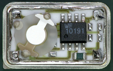
Wikipedia also provides this image of the insides of a crystal oscillator:

enter image description here

To the left in that picture is the crystal (the round thing.) To the right is an IC that provides amplification to make the oscillator. A crystal oscillator has three connections: Power, ground, and output.

Your circuit assumes a simple crystal. The item shown as Q1 in your schematic is simply a piece of quartz in a box with pins. It needs additional circuitry to make an oscillator.

The 7404 provides the amplifier that you need to make an oscillator with a frequency controlled by the crystal.

In this case, look at the 7404 buffers as inverting amplifiers. Two of them in series is a non-inverting amplifier.

To get oscillation, you need positive feedback. The circuit you show provides positive feedback through the crystal - but only at the resonant frequency of the crystal.

The first two 7404 inverters (D1(LN1)A and D1(LN1)B) are the oscillator that generate the signal, with Q1 setting the frequency.

The third inverter (D1(LN1)C) provides a buffer between the oscillator and the rest of the circuit.

D1(LN1)C has two jobs:

  1. It sharpens the oscillator output from a sine wave into a square wave.
  2. It prevents the load from other parts of the circuit from interfering with the operation of the oscillator.

R1 is probably a little bit tricky. It influences the start up behaviour of the oscillator. The correct value will depend somewhat on the exact 7404 model that you use and the crystal itself. Some combinations of crystal and inverter will oscillate without it, some will need a particular resistance value to make the oscillator start reliably.

\$\endgroup\$
3
\$\begingroup\$

That is one of the standard ways to bulild a crystal oscillator. In many literature that is called a "series" resonant crystal oscillator.

  1. The resistor biases the inverter into linear are of operation where it has the highest gain. Based on the value being so absurdly low, it is most likely used with TTL chip, not CMOS chips. The resistor value would vary based on logic chip family.

  2. The second inverter is for driving the feedback via crystal, the crystal is used as the feedback element to set the oscillation frequency. Third inverter buffers the signal so connected loads don't affect the frequency.

  3. Yes there is a feedback loop with 360 degrees of phase shift.

Simply put, it's a crystal oscillator made of discrete components. Inverters are used as high gain inverting linear amplifiers. You'll need correct type of logic chips and crystal to make it oscillate and at the right frequency. If it does not work then try different parts. Those circuits are extremely quirky, it would be maybe better to build a Pierce oscillator instead, or simply buy a clock oscillator module instead of debugging why it does not work. But it is an interesting circuit to build.

\$\endgroup\$
0
\$\begingroup\$

There are certainly many ways to make a crystal oscillate, many more accurate than this without caps. and simpler with a XO chip at low cost at your frequency.

(Search lots of solutions on this site)

This circuit is not the best and is primitive ( no tuning caps, no 10uW power limiting series R for Xtal, unterminated CMOS PRE inputs) but seemed to work at the time so he put his happyface icon on it. ;)

But you may want f/2 for making biphase gated clocks at 2f for Row Address load and memory reads depending on your design.

But here is some feedback on each signal.

enter image description here

\$\endgroup\$
6
  • \$\begingroup\$ The circuit itself is from the 1980s - it is either a reverse engineered schematic or a section of the original. In either case, it isn't a new thing that some beginner did, but rather something a qualified engineer did back in the day. It looks crude and crummy today, but it was normal back then. \$\endgroup\$
    – JRE
    Commented Apr 14, 2021 at 13:44
  • \$\begingroup\$ Yes I assumed that too, but even back then , all Sr. Designers knew about tuning caps and Xtal power limits, and documentation stds. (At least in those I worked for) in the late 70’s and 80’s, self biasing 74HC’s is not that reliable as shown \$\endgroup\$
    – D.A.S.
    Commented Apr 14, 2021 at 13:52
  • \$\begingroup\$ Take a closer look at that thing. The "Leningrad" is a clone of the Sinclair ZX Spectrum. Penny pinching was the norm. \$\endgroup\$
    – JRE
    Commented Apr 14, 2021 at 13:54
  • \$\begingroup\$ But not best in class. We had to learn quickly , by mistakes. \$\endgroup\$
    – D.A.S.
    Commented Apr 14, 2021 at 13:54
  • \$\begingroup\$ I suspect the following : it is reverse engineered schematics by a hobbyist so part types regarding TTL/CMOS may be inaccurate. Series resonant oscillators do not need tuning caps. That is why you can buy crystals with either a specific load capacitance rating, or "series operation". Besides the actual frequency would not matter much, as long as it works. \$\endgroup\$
    – Justme
    Commented Apr 14, 2021 at 14:02

Your Answer

By clicking “Post Your Answer”, you agree to our terms of service and acknowledge you have read our privacy policy.

Not the answer you're looking for? Browse other questions tagged or ask your own question.