0
\$\begingroup\$

I am currently building a small Z80 microprocessor system and require some kind of clock generation. It is not my first design: Earlier I used an Arduino pin that generated a slow clock or a 555 timer. However, earlier designs only included the Z80 and some RAM and ROM.

Now I want to expand upon that and include peripherals. That's why I chose a 3686.4 kHz Quarz, so that I can divide it later via a frequency divider to not only generate my processor clock but also my UART clock.

I did some research on the internet, read some books and schematics and found out that most use a pierce oscillator or a series resonant oscillator. For my design I want to use plain 74xx or 74LSxx chips, because I have them around and ready to use. Fortunately, most books for the Z80 and websites also built them using 74xx chips. So I tried to rebuilt them. My pierce design did not work at all, so I quickly changed my setup to a series resonant oscillator.

For my oscillator I use a single 7404 inverter that has a 100 nF decoupling capacitor attached between 5V and GND. Then I simply copy-pasted the circuit from "Build Your Own Z80 Computer" page 94. I added the capacitor after seeing it on many schematics and without it, it didn't start oscillating anyways. I attached my schematic below (it does not show the decoupling capacitor between 5V and GND)

Schematic of my oscillator with a 7404

Now when I apply some voltage to this circuit it indeed starts to oscillate. However, the frequency is not stable at all, seems to be 200 kHz below the stated one and the duty cycle is not at all 50%. You can see my logic analyzer output below. Logic Analyzer output

Whereas the logical high state seems to be quite stable with one unstable cycle seeable at the right end of the graph, the off state varies quite a bit.

Frankly speaking, I do not know how to fix this as I have not much experience with oscillators. However, I have a feeling that the capacitor does have quite an influence. When I changed it from 100 pf to 22 pf the frequency was completely unstable. When I changed it to a higher value, I didn't see much difference at all. I also tried to exchange the 7404 with an 74LS04 as some schematics use it, but that didn't change anything.

If somebody can point out my mistake to me I would be very glad.

Additional Info: The data sheet of the crystal calls states CL=20pf and Rr < 120 Ohm.

\$\endgroup\$
7
  • 1
    \$\begingroup\$ See electronics.stackexchange.com/questions/363305/… answers. It works much better with CMOS gates. \$\endgroup\$
    – crj11
    Commented Dec 22, 2019 at 19:48
  • \$\begingroup\$ @crj11 The OP may want to stay "retro" with the build. Just the fact of having a 7404 in hand suggests that to me. But it could just be ignorance, too, and only seeing old Z80 diagrams. \$\endgroup\$
    – jonk
    Commented Dec 22, 2019 at 20:21
  • \$\begingroup\$ Trunyx, as already stated you probably want to shift to a parallel circuit. Also, note that the resistors going from inverter output to inverter input set the bias point. When you do get around to using a parallel arrangement, it may also be important that you work on getting the biasing point where you need it to get stable and equal periods of on and off. (Actually, it's also important for your existing circuit.) \$\endgroup\$
    – jonk
    Commented Dec 22, 2019 at 20:26
  • \$\begingroup\$ @jonk Yes, I indeed intend to stay "retro". I know that with more modern solutions some things would be easier, but I am quite fascinated by older technology. My earlier builds used more up to date parts, but also never included an oscillator circuit. Right now I struggle to get the parallel setup working as I do not quite understand how to choose the resistors for the bias point. I am following this guide \$\endgroup\$
    – Trunyx
    Commented Dec 22, 2019 at 21:24
  • \$\begingroup\$ Since you have prior experience, I assume you know enough not to use a solderless protoboard for on oscillator like this. \$\endgroup\$
    – jonk
    Commented Dec 22, 2019 at 21:31

5 Answers 5

6
\$\begingroup\$

Something you need to be careful with when using the Saleae device is that it takes samples, not continuous measurements. At 24MHz it is taking a sample every 41ns or so. The period for your 3.686MHz clock is 271ns. I'd expect to see some aliasing as the ratio between the two is 6.6:1.

An oscilloscope would be a better testing option.

\$\endgroup\$
2
\$\begingroup\$

This is just to teach you why your TTL oscillator fails in this Pierce series resonant mode, you have to see how TTL works.

Fixes

  • change 100pF to 10nF to eliminate phase shift at 3.5MHz
  • add 2.4k input to ground to pull output >> 2.0V towards 2.4V (opt.)

The impedance of 100pF is too high and = 1 k @ 3.5MHz so you get a bad 45 phase shift twice and the non-inverting loop is no longer in phase to satisfy the Barkhausen criteria to oscillate.. (Av>1 at 0 deg.)

This is the design of the TTL Inverter 7404 with 2 resistors added on input and coupling cap.

enter image description here

They changed the currents, resistor values and bias methods later with Schottky diodes but the current ratios were always 10:1 and the input threshold was/is always 2 diode drops or Vbe drops = 1.5V +/-0.1 depending on bias current and temp.

Parallel resonant XTAL OSC or XO's are best used with CMOS up to 20MHz and Series resonant transistor XO's above this f to avoid sensitivity to stray capacitance.

\$\endgroup\$
1
  • \$\begingroup\$ Thanks for you explanation. However, it seems my crystal is not made to work in a series resonant oscillator but rather a parallel resonant oscillator. So I will need to fundamentally change my circuit \$\endgroup\$
    – Trunyx
    Commented Dec 22, 2019 at 22:59
2
\$\begingroup\$

I looked up an old Z80 computer design from the 80ies (the mc CP/M-Computer). It also used an oscillator with 7404 gates:

Oscillator of the mc-CP/M-Computer

The capacitor used there is 10nF. So I guess values in the pF range are much too small.

\$\endgroup\$
0
\$\begingroup\$

You have a series resonant oscillator, and the crystal is meant to be used with parallel resonant oscillator as it requires 20pF load capacitance. Either change to parallel resonant oscillator, or change the crystal to one meant for series resonance.

\$\endgroup\$
0
\$\begingroup\$

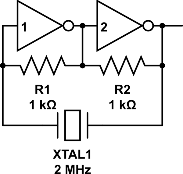
I have a 2 MHz crystal, and a 4 MHz, not your 3.odd MHz. With odd contacts on a breadboard, I first could not make your circuit work, but I have one that is almost like yours, just removing that capacitor altogether. And it works perfectly every time without that capacitor.

When I use you 100 pF I get a very dirty signal on the 2 MHz. If I increase the capacitance to 10 nF, as someone suggested it looks better. But then, the higher the capacitance there goes, at MHz frequencies the more it approximates just having no capacitance at all.

One commented under my earlier version of this answer said my circuit here doesn't work, but it does, I just had my analog scope settings wrong so I measured 4 times higher frequency. But that was just a newbie's operator error.

Frankly, I don't see the point of all this extra stuff if this here works much more reliable and simple. No capacitors to worry about frequency.

schematic

simulate this circuit – Schematic created using CircuitLab

I don't know why everybody is showing the more complex and harder to get to work schematics. Possibly it has something to do with wearing out the crystal.

\$\endgroup\$
3
  • 1
    \$\begingroup\$ As per your own question here, this circuit does not work as expected. \$\endgroup\$
    – StarCat
    Commented Jun 21, 2020 at 11:56
  • \$\begingroup\$ It was the only one that worked for me, albeit at a weird frequency. :) \$\endgroup\$ Commented Jun 23, 2020 at 17:16
  • \$\begingroup\$ Actually, it did work 100% perfectly! As on that other question, the actual answer was nothing magic at all, I simply didn't have my scope settings right and gladly I posted a picture and gladly @glen_geek discovered my error. So, yes, this circuit works flawlessly for me and none of the others did so far. \$\endgroup\$ Commented Jul 4, 2020 at 18:42

Your Answer

By clicking “Post Your Answer”, you agree to our terms of service and acknowledge you have read our privacy policy.

Not the answer you're looking for? Browse other questions tagged or ask your own question.