What would be the simplest way without using a microcontroller to make a stop light circuit. All it must do is go from Green -> Yellow -> Red.
-
1\$\begingroup\$ Does simple mean discrete components only, or do you want to use integrated circuits like a 555 timer? Also, a PIC is only one kind of microcontroller - You could also do this with an Atmel ATtiny, for instance. Are you looking for other micros? \$\endgroup\$– Kevin VermeerCommented Oct 25, 2010 at 14:36
-
\$\begingroup\$ I think he means microcontroller by PIC. \$\endgroup\$– KortukCommented Oct 25, 2010 at 15:40
-
\$\begingroup\$ Since he hasn't objected to that statement in 24 hours, I assume that it was what he meant, and edited the question to reflect this. Feel free to roll it back if it was not what you meant. \$\endgroup\$– Kevin VermeerCommented Oct 26, 2010 at 17:27
4 Answers
You could do it with a 555 timer and a counter:
-
\$\begingroup\$ Is there anything easier than that with less componets? \$\endgroup\$– leisxCommented Oct 25, 2010 at 13:40
-
13\$\begingroup\$ 3-way switch, 3 bulbs and a battery? \$\endgroup\$ Commented Oct 25, 2010 at 13:48
-
\$\begingroup\$ I agree with Joby - unless you want it automatic, in which case you'll need a few more components for sure \$\endgroup\$– JimCommented Oct 25, 2010 at 15:33
-
\$\begingroup\$ Not sure how they used to do it, but I could imagine a geared motor turning brushes on a ring. Easy synchronization for multiple lights by stacking up multiple levels. \$\endgroup\$– Nick TCommented Oct 26, 2010 at 18:18
The minimal autonomous circuit, I think, involves at least a 555 (or another astable multivibrator, some TRC circuit perhaps) and a counter (or some opamps or diode-diode logic).
I tried a circuit right now, it includes a astable mv (you can also use a 555) and one op-amp: circuit simulator
-
\$\begingroup\$ thanx for the edit, I didn't know that trick \$\endgroup\$– J.P.WackCommented Oct 25, 2010 at 18:52
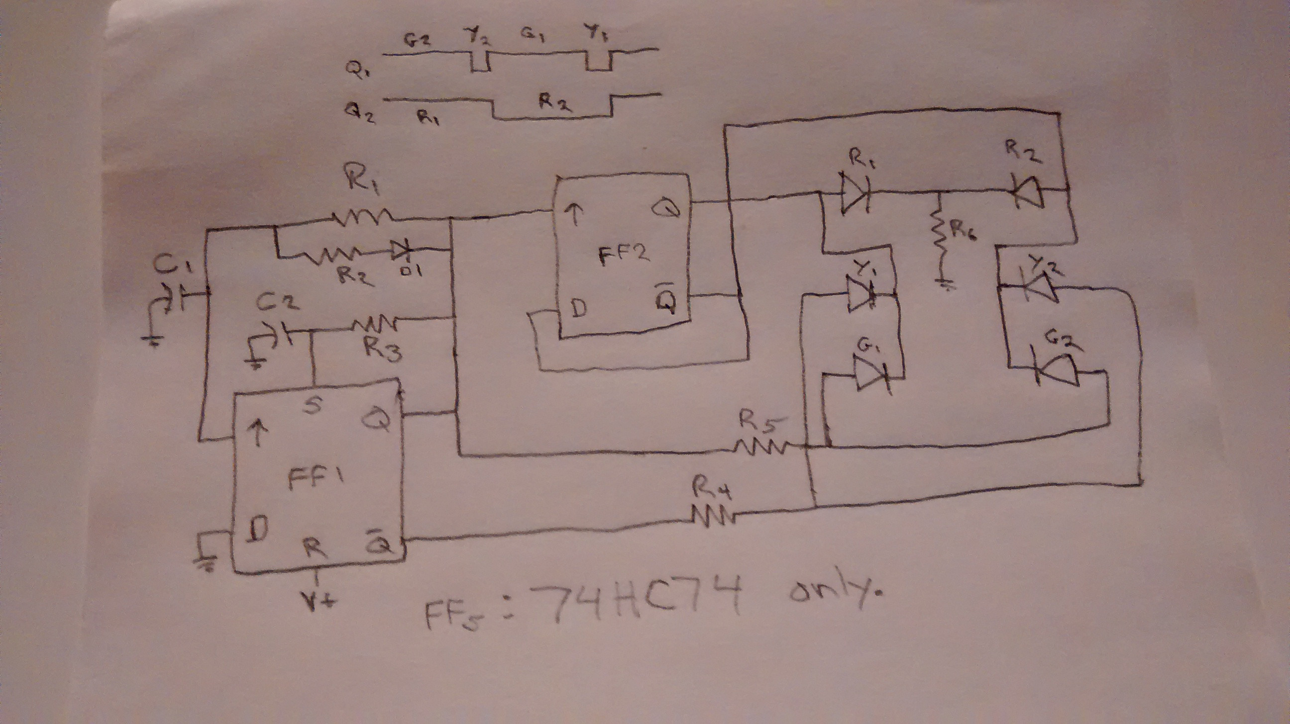
Eight and a half years too late for leisx but there is a simple circuit that provides the correct sequence and timing, unlike the other answers. I already knew the simplest way, but for fun created a new circuit that is about as simple. It is built on a 74HC74 D flip-flop; one section forms an oscillator and controls the green and yellow LEDs; the other toggles to control the red LEDs. ( Note: this only works with 74HC flip-flops, not 4013 etc.) For FF1, R1 and C1 determine the time the green LED is on, and R3 and C2 determine the time the yellow LED is on. R2 discharges C1 quickly when the Q output is low, 10K is a good value. The oscillator could be made with one cap and three resistors, but would require a nonpolar cap and the G and Y times could not be set independently, so I opted for the version shown. R4,5,6 set the LED current so you can match the brightness of the different colors. ( The LEDs could be wired so only one resistor is used but this requires six LEDs of equal brightness.) The little timing chart shows the sequence, which is correct for North America.
You are going to want a very slow clock source, but this should be relatively easy to do with next state logic and 3 flip-flops (clearly you only need two, but one hot encoding makes it easy for 1 extra flip-flop)
just feed the flip flops to each other in a loop, have it reset so that one goes to green, and you have it.
-
\$\begingroup\$ Please note you still need a simple clock source. \$\endgroup\$– KortukCommented Oct 25, 2010 at 15:40
