1
\$\begingroup\$

I've wired a set of WS2813 leds to a Raspberry Pi. The led strip is found here: https://www.amazon.com/gp/product/B077J27Y4X/ref=ask_ql_qh_dp_hza

When I have this strip connected via the short cable/JST connectors that came with the strip all works well. But when I connect an approximately 3' cable between the Pi and the led strip it no longer functions...just the first few leds light with a very random pattern (not as programmed). I've removed the wire and soldered the JST connector back and the strip works fine again so I know the strip is still functional after my soldering skills were applied to it. This is the wire I'm using...https://www.amazon.com/gp/product/B07SJGHMX2/ref=ppx_yo_dt_b_search_asin_title?ie=UTF8&psc=1

I've tested the wire with a multimeter. There is definitely continuity on all four wires. I checked it with the continuity mode and resistance mode. I've tested the voltage drop within the wire, coming out of the Pi it is approximately 5.2V and after at the input of the strip with the 3' wire connected it is about 5.1V, still higher than the required 5V. There is a similar voltage on the DI and BI pins as well which is about .15 to .2 volts (I'm assuming this reads lower because the Pi is rapidly signaling these pins).

I'm just a hobbyist learning from the Internet and this one has me stumped...I can't find anything that can clue me into what is happening and why. Your help is greatly appreciated.


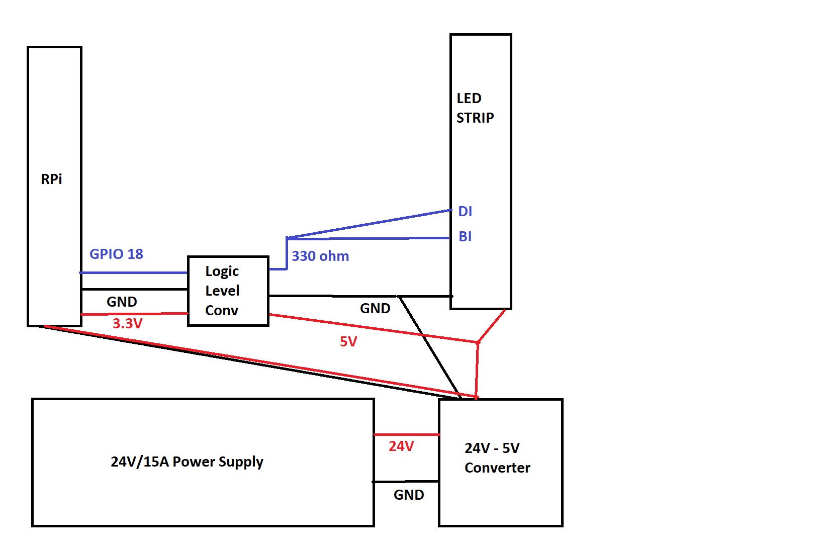
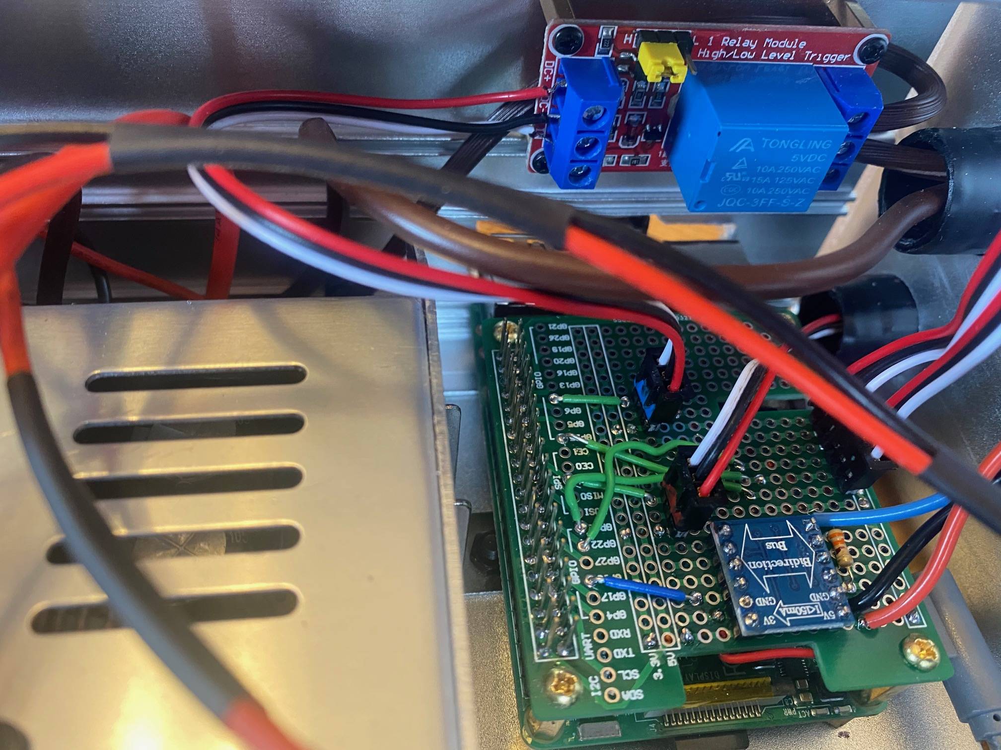
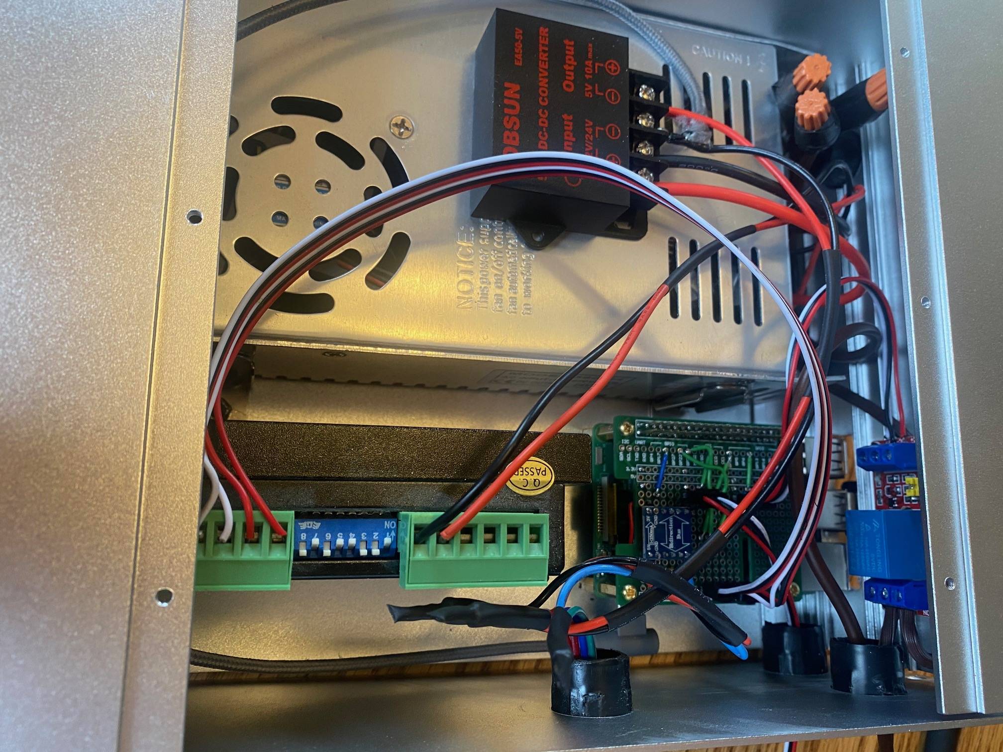
As requested here are the wiring diagrams with two photos to show the actual circuits.

Wiring Diagram Close up of Pi/Logic Level The Entire Project

\$\endgroup\$
7
  • 1
    \$\begingroup\$ The WS2813 has two data pins. So four wires, one for +5V, GND, the DI and the BI pin. From my Pi - I have pin 18 connected to both the DI and BI pin. So yes, from controller only 3 wires. But the four wires are to match the JST connectors. Either way, it works when I use the connector which makes for about 6" of wire between the Pi and strip. But when I add my 3' cable it displays this behavior. Thanks! \$\endgroup\$
    – Aaron Long
    Commented Apr 29, 2021 at 0:19
  • \$\begingroup\$ To clarify my last comment. From the Pi - I'm only connected to pin 18 to the DI/BI pin on the led strip. This goes through a logic level converter to convert the Pi's 3.3V to 5V which the strip requires. The 5V and GND are coming from an independent power source. \$\endgroup\$
    – Aaron Long
    Commented Apr 29, 2021 at 0:32
  • \$\begingroup\$ Try to connect BI to ground. \$\endgroup\$
    – user263983
    Commented Apr 29, 2021 at 0:34
  • \$\begingroup\$ A suggestion was made for a diagram and pictures...I've added now. \$\endgroup\$
    – Aaron Long
    Commented Apr 29, 2021 at 0:55
  • \$\begingroup\$ @user263983 - I tried that and no change in behavior. Thanks for your continued help! \$\endgroup\$
    – Aaron Long
    Commented Apr 29, 2021 at 1:36

1 Answer 1

1
\$\begingroup\$

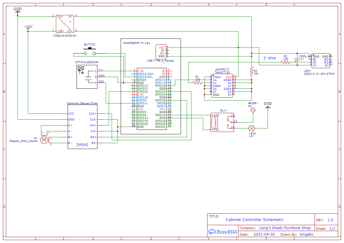
Thank you @Kartman for your suggestion. While I couldn't find the 74HCT367 logic shifter in a DIN package your help pointed me enough in the right direction so I could figure the rest out. First, I added the resistor to the DI pin and then a 2000uF capacitor between Vcc and GND. Still no luck. Then I switched out the bidirectional translator and replaced with the 74AHCT125 from Adafruit and a 220ohm resister by the Pi and then by the strip. I had a lot of random flickering which indicated the data signal was still getting corrupted (not power) so I added a 10K resistor (I think this is a pull-down resistor) to my the enable pins on the shifter (which have to be low to enable). While I still don't fully understand why the previous circuit worked without the 3' wire in between it is working now. Your help is appreciated! Here is an updated circuit diagram for those who might stumble on this thread in the future.

Circuit Details

\$\endgroup\$

Your Answer

By clicking “Post Your Answer”, you agree to our terms of service and acknowledge you have read our privacy policy.

Not the answer you're looking for? Browse other questions tagged or ask your own question.