2
\$\begingroup\$

Edit: Used wrong resistor at R_BAT1. The schematic was correct, the part I used was wrong.

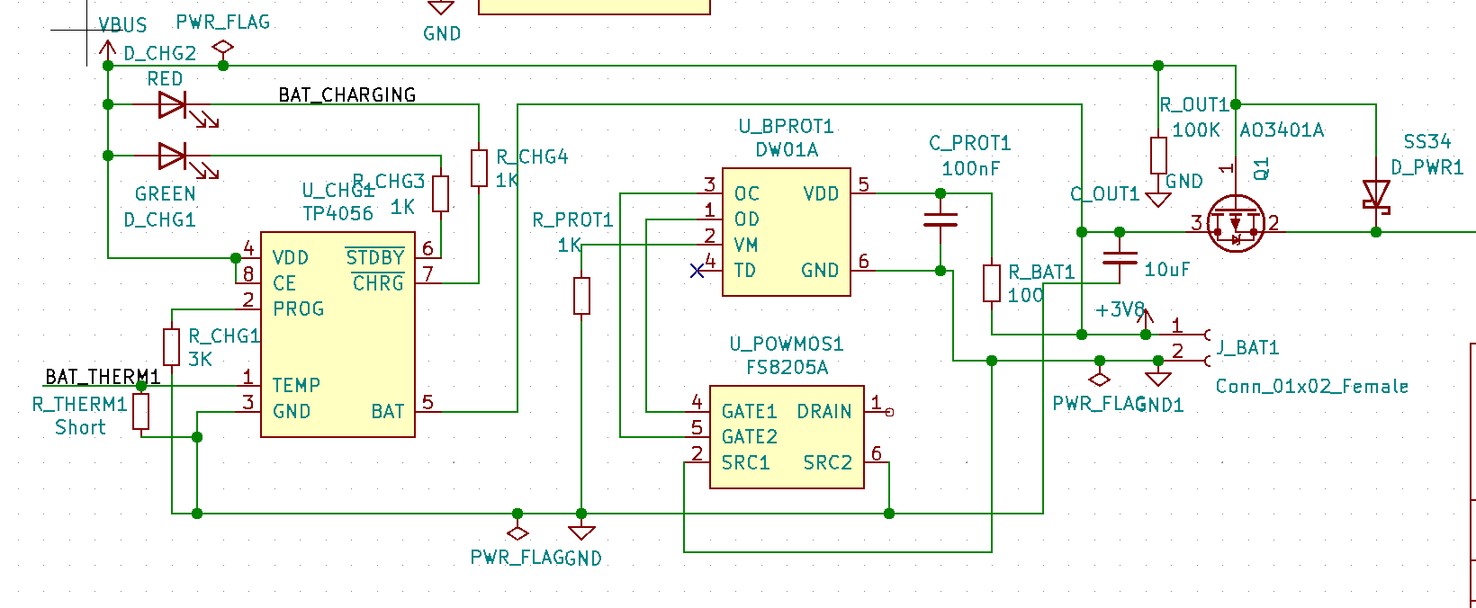
I am using the following charging circuit. It is the standard circuit taken from the datasheets. But it is not working.

enter image description here

The line on the right leads to an LD3985M33R LDO and then to a microcontroller. All the other components are working fine, if I bypass the DW01A by shorting the battery ground and common ground - the TP4056 charged both my 18650 batteries fine and stopped charging once it was done, the switching circuit with AO34021A works fine, the LDO regulates perfectly and the microcontroller works fine as well. If I remove the short, the battery gets disconnected.

I bought a blue TP4056 module that has the same circuit (I traced the leads with a multimeter) and it works fine without bypassing DW01A. I took the DW01A and the C_PROT1 capacitor from that board and used it in my board. My board still does not work. I placed the DW01A and C_PROT1 from my board on the purchased TP4056 module and the module works fine.

I am stumped and unable to figure this one out. I am probably missing something obvious. Could you please help me? Thanks in advance.

\$\endgroup\$
4
  • 1
    \$\begingroup\$ What are the voltages on the OC and OD lines to the MOSFETs while you're trying to charge? \$\endgroup\$
    – Finbarr
    Commented May 21, 2021 at 18:35
  • \$\begingroup\$ @Finbarr Thank you for helping. I found the issue. The cause was me being an idiot and giving the wrong part number for resistor R_BAT1. I gave the code for a 10MOhm resistor instead of a 100 Ohm resistor and they placed that component. I guess the DW01A was not sensing any current from the battery and hence cutting it off. I replaced it with a 100 Ohm resistor from the module I bought and it works perfectly. I will delete this comment tomorrow so that people don't waste time reading this. Thanks again! \$\endgroup\$
    – Uday
    Commented May 22, 2021 at 16:39
  • 2
    \$\begingroup\$ @uday you should convert that comment to an answer and accept it. Its good to keep around as someone some day will end up googling a similar question and find yours. \$\endgroup\$
    – Passerby
    Commented May 22, 2021 at 16:47
  • 1
    \$\begingroup\$ It's not that the DW01 won't be sensing current, it's that it'll hardly be getting any supply voltage, which means it turn that it won't be able to output enough gate voltage to turn either MOSFET on. The typical supply current of 3uA going through a 10M resistor would drop 30V which is clearly not going to happen. \$\endgroup\$
    – Finbarr
    Commented May 23, 2021 at 9:57

1 Answer 1

2
\$\begingroup\$

I found the issue. I gave the wrong part number for resistor R_BAT1. I gave the code for a 10MOhm resistor instead of a 100 Ohm resistor and the SMT assembly placed that component. I guess the DW01A was not sensing any current from the battery and hence cutting it off. I replaced it with a 100 Ohm resistor, tested it over a few charge and discharge cycles and it works perfectly.

\$\endgroup\$

Your Answer

By clicking “Post Your Answer”, you agree to our terms of service and acknowledge you have read our privacy policy.

Not the answer you're looking for? Browse other questions tagged or ask your own question.